Pulsation Analysis For Reciprocating Compressors According to API 618
Pulsation analysis for reciprocating compressors (according to API 618) and centrifugal compressors
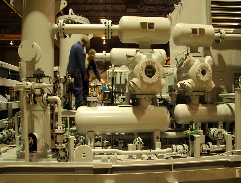
Within an industrial plant, it is frequently necessary to increase the pressure of a flow. To achieve such an increase in pressure, compressors and pumps are used, with compressors being used for gaseous flows and pumps being used for liquids.
Compressors are available in a number of forms, namely reciprocating, axial, and centrifugal. Within a reciprocating compressor, the pressure rise is generated by compressing a volume of gas within a piston. Whilst in a centrifugal or axial compressor the pressure rise is achieved by doing work on the gas using rotating aerofoils or blades.
Both of these methods will cause pressure oscillations in the flow, due to the passage of the rotating components or the intermittent nature of the flow from the cylinder of a reciprocating compressor. Such pulsations within the flow can lead to unbalanced forces and acoustic resonance modes within the piping which can potentially cause fatigue failures. Undesirable vibrations can also reduce the efficiency of downstream equipment and lead to errors in flow measurement results.
Design Codes: API 618 and VDI 3842
The industry standard design code API 618 provides guidelines for the maximum pressure vibrations due to reciprocating compressors. Likewise, the VDI 3842 code also has guidelines for the maximum pressure fluctuation amplitudes. These experienced-based limits can be used to identify excessive, potentially damaging, pressure pulsations within the piping, due to a compressor.
Typically, given the intermittent nature of the flow, reciprocating compressors will tend to cause larger amplitude pulsations than centrifugal compressors. Centrifugal and axial compressors in contrast, on account of their higher number of rotations per minute (rpm), will cause pulsations of a higher frequency.
By conducting a pulsation analysis of the system, Dynaflow Research Group (DRG) can help identify excess pulsation pressures at the design stage. If a potential issue is identified, DRG will identify the source of the problem. DRG is then adept at using its vast experience to propose practical and economically viable engineering solutions.

Sizing Compression Dampeners
Excessive pressure pulsations due to a compressor can often be reduced using compression dampeners. Compression dampeners are bottles that are connected in the piping upstream and/or downstream (depending on the requirements) of the compressor.
The bottles serve as surge volume, with a comparatively large volume compared to the pipe cross-section and pipe nozzle, meaning that entering pulsations are dampened. Theoretically, pulsations from a compressor can be dampened to any desired degree provided that a bottle of sufficient volume is used.
Bottles are frequently used with reciprocating compressors, on account of the relatively large amplitudes to be damped. Thus, the API 618 design code provides design rules for the sizing of a bottle. However, the designer must also consider that the bottle itself will also have an acoustic resonance frequency. Incorrectly sizing the bottle could therefore lead to a situation, whereby the pulsations from the compressor are amplified rather than dampened.
From our experience, we at DRG, have built up an understanding of the designing and sizing of compression dampeners. Therefore, DRG fully understands the practical limits and economic considerations, which dictate the maximum and minimum bottle dimensions, and the level of pulsation dampening that can be achieved.
Case Study: Pulsation Analysis of a Metering Proving Facility
Dynaflow Research Group (DRG) has conducted a pulsation analysis of a new measurement proving facility. This proving facility had been designed to calibrate flow measurement equipment; predominantly turbine and ultrasonic flowmeters. Given the accuracy desired of such equipment, there needed to be no significant pulsations as a result of the upstream compressor present in the calibration area.
The measurement station was connected to an existing natural gas supply line, which was fed by centrifugal compressors. The piping within the proving facility has acoustic resonance modes, which could be excited by the pulsations from the compressor and thereby lead to large amplitude pressure oscillations. Should this occur then there was a risk of excessive noise levels and vibrations of the structure and piping.
The aim of this pulsation study was thus to assess if the pulsations from the compressor had the potential to dangerously excite one or more of the acoustic resonance modes. The proving facility has a number of different operating scenarios, with a range of filters, heat exchangers, and measurement devices all in operation. Within the analysis, all of the operating scenarios were considered and an analysis was done for the most critical scenarios. Given that the precise compressor characteristics were unknown, DRG conducted this study across a range of pulsation amplitudes and frequencies. The limits of this investigation were therefore based on the experience of DRG and the widely used design codes.
As a result of the analysis, DRG was able to conclude for our client that the upstream compressor should not lead to excessive pressure amplitudes within the piping. Thus, according to the design codes and DRG’s experience the proving facility was judged to be fit for purpose.