The J-integral Approach in Elastic-Plastic Fatigue Analysis by Tammo Dukker
In a fatigue analysis one would like to investigate the susceptibility of a structural component to crack propagation under cyclic loading to determine the number of cycles until a failure occurs. Common techniques applied in a fatigue analysis follow from the results of a linear elastic analysis with limited plasticity assumed. For cracks in critical components under high stress however, high plasticity could be present and an elastic plastic analysis will provide a more accurate estimate. Rice, J (1968) presented a novel technique within this regime by introducing a path independent integral around a crack tip: the J-integral [1]. This J-integral is representative of a potential energy release with respect to crack extension and was coined by Rice as [1]:
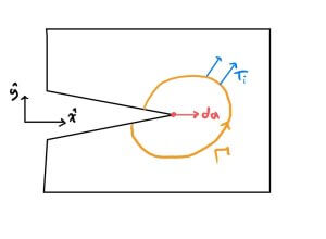
\[J = \int_\Gamma (Wdy-\vec{T}\cdot\frac{\partial\vec{u}}{dx}ds)
\]
Where $\Gamma$ is a curve surrounding the notch tip starting on the bottom crack surface and ending on the top crack surface as in figure 1,
$\vec{T}$ is the traction vector defined with the outward normal from $\Gamma$: $T_i = σ_{ij}n_j$, $\vec{u}$ is the displacement vector and W is the strain-energy density defined by
\[W = \int_0^\epsilon \sigma_{ij}d\epsilon_{ij}\]
where $\epsilon_{ij}$ is the infinitesimal strain tensor. In essence, as Bowles (1980) notes, the J-integral can be viewed as the plastic version of the linear stress intensification factor K used in linear fatigue analysis [2]. In the linear region they are related by
\[\Delta J = \frac{\Delta K ^2(1-\nu^2)}{E}\]
Where E and $\nu$ are the young’s modulus and Poisson’s ratio respectively.
The power of the J-integral lies in its path independence. Any path around the crack tip as defined in figure 1 yields the same value for J. Thus the stress field around a crack tip delivers one unique value for the J-integral at that crack tip. With finite element analysis the evaluation of the J-integral through the first equation above is relatively simple seeing as the numerics provides us with a stress and a strain field in our geometry. With the J-integral in hand we can then link our values of J to crack tip propagation rate with empirical data. We draw the analogy with linear theory where one uses Paris’s law to relate stress intensification factor to crack growth rate:
\[\frac{da}{dN} = C\cdot(\Delta K)^m\]
as we saw earlier J is in essence the nonlinear analog of K so we get:
\[ \frac{da}{dN} = C\cdot(\Delta J)^m\]
Here the fitting parameters C and m are material and geometry dependent. Dowling (1976) for example gives the formula for fatigue crack growth rate in centre cracked A533B steel as [3]:
\[\frac{da}{dN} = 2.5\cdot 10^{-8}(\Delta J)^{1.56}\]
With this, one can determine the number of cycles dependent on the tolerable crack size in your system; thereby completing a nonlinear, plastic fatigue analysis of your system.
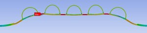
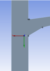
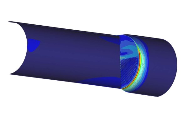
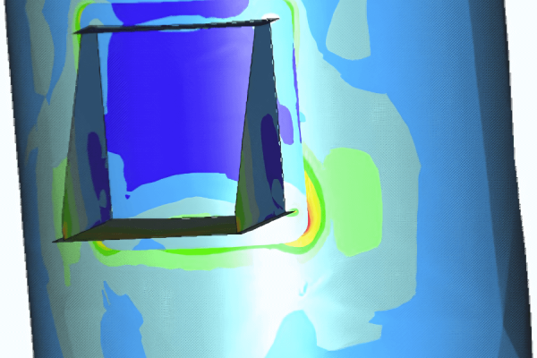
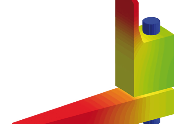
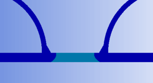
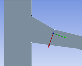
A recent application of this technique performed by Dynaflow for a client was in the fatigue analysis of a half pipe heat exchanger jacket with the finite element software Ansys. A 2D axis-symmetric model was built and under the design operating conditions high stresses and some plastic straining was observed between the coils as is showcased in figures 2 & 4. A number of crack locations were trialed two of which are shown in figures 3 & 5. Within Ansys one can define the crack tips and crack propagation directions and directly calculated the J-integral around these crack tips and thus, with an appropriate formula, calculate the number of cycles until failure if a crack were present at that location in the half pipe heat exchanger.
For more information, please contact:
Edwin Schimmel
Project Engineer
Phone: +31 85 058 0046
References:
- [1] James R Rice. A path independent integral and the approximate analysis of strain concentration by notches and cracks. Journal of Applied Mechanics, 1968.
- [2] CQ Bowles. The j integral approach in elastic-plastic fatigue crack propagation. In Advances in Fatigue Science and Technology, pages 467–488. Springer, 1989.
- [3] Norman E Dowling. Geometry effects and the j-integral approach to elastic-plastic fatigue crack growth. In Cracks and fracture. ASTM International, 1976.
Note on author: Tammo Dukker is an engineering intern within our consultancy branch at Dynaflow Research Group. He is pursuing an MSc in Applied Physics at TU Delft with a focus on fluid mechanics. He has a keen interest in the application of fluid mechanics in the energy industry and offshore & coastal domains.