Introduction
In the context of a compression station project, DRG conducted a comprehensive static stress analysis encompassing the plant inlet, slug catcher, and filter areas. This analysis was imperative for ensuring the structural integrity and functionality of the newly constructed compressor station.
Analysis
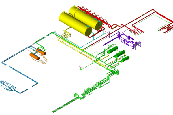
Using the sophisticated pipe stress software CAESAR II, a static stress model was meticulously crafted. This model delineated the entire system, commencing from the plant inlet headers and extending to the outlet of the filters. The complexity of the model spanned both underground and aboveground piping sections, accurately reflecting the real-world scenario.
To incorporate the influence of soil mechanics, bilinear springs were strategically employed in the axial, horizontal, and vertical directions within the model. These springs were calibrated based on soil data furnished by the client, specifically tailored to the soil composition pertinent to the compression project. Adhering to the guidelines outlined in NEN3650-1, the soil mechanics were meticulously simulated.
Careful consideration was given to selecting parameter values within the ranges pertinent to the soil type. This ensured alignment between the calculated vertical bedding constant and the measured value derived from NEN3650-1 calculations. Additionally, long-term soil settlements were factored into the analysis, as per the settlement information provided by the client.

Results
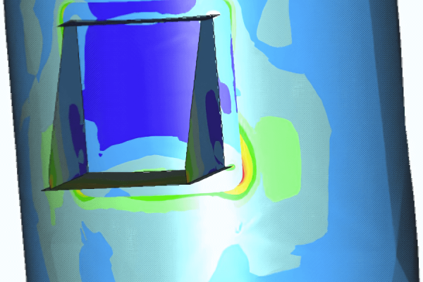
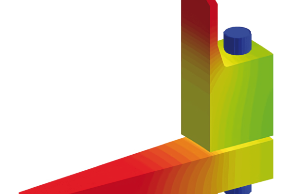
The results of the analysis were reassuring, with stresses across various load cases and assumptions consistently below the allowable stress limits stipulated by the ASME B31.3 code. Of particular note was the identification of the 8” interconnecting piping of the slug catcher as the most stressed and sensitive component. A supplementary soil sensitivity study was undertaken, affirming that even under adverse variations in soil characteristics, stress escalation remained within acceptable bounds.
Moreover, all nozzle loads remained comfortably below allowable values, obviating the need for aboveground pipe support. However, it was deemed necessary to provide support for the 30” filter lines with a concrete slab, particularly before the bend where these lines ascend vertically to the aboveground level. This measure was essential to mitigate filter nozzle loads and ensure compliance with acceptable levels, especially under long-term soil settlement load cases.
Throughout the system, meticulous checks were conducted on all flanges to ascertain their equivalent pressure, ensuring adherence to their pressure ratings without exception.