Pulsation Analysis for Reciprocating Equipment
Pulsations caused by reciprocating equipment such as pumps and compressors can lead to vibrational problems in piping systems. Several API standards provide guidelines to ensure vibrations don’t exceed failure limits.
At Dynaflow Research Group we offer engineering solutions for complex compressor and pump issues, including pulsation analysis, mechanical response studies, structural analysis, and flow calculations.
Our team of engineers has expertise in providing API 618 and API 674 compliant solutions for reciprocating compressors and pumps, respectively, and often apply VDI 3842 for mechanical response analysis and vibrations.

PULSATION ANALYSIS SERVICES
Comprehensive Pulsation and Vibration Analysis for Reciprocating Equipment
A pulsation study according to API 618 and API 688 for reciprocating compressors, consists of several checks on pulsation levels and shaking forces that need to be assessed to have a safe and efficient operating system.
To prevent excessive vibrations, DRG’s approach is to investigate both the acoustic resonances within the system as well as the mechanical natural frequencies. Vibrations will always be due to an interplay between acoustic and mechanical modes. The API code defines three different design approaches.

- Design Approach 1 has been removed from the latest version of API618 (edition 6 from 2024) and is no longer available.
- Design Approach 2 involves performing an acoustic analysis to determine pulsation levels in the piping and on the compressor flange. The non-resonant shaking forces are assessed as well and resonance between the acoustic excitation and structural mechanical modes is prevented by introducing separation between the acoustic and mechanical modes.
- Design Approach 3 combines the acoustic study with a mechanical response study. The calculated forces from the acoustic study are applied to a mechanical model and a stress assessment is performed for the cyclic stresses. This is a more detailed analysis and can lead to a more economical design compared to design approach 2.
The industry standard design code API 674 provides guidelines to avoid pulsations from a reciprocating pump having a detrimental impact on a system.
By conducting our pulsation and mechanical response studies according to this code, Dynaflow Research Group (DRG) can establish if pulsations are a potential issue for your system.
The API 674/675 code for reciprocating pumps provides two different design approaches. Depending on the requirements of the client, the most suitable design approach can be conducted.

- Design Approach 1 of API 674 sets limits on pulsation levels (C.1.5), minimum pressure (C.1.6), and maximum pressure (C.1.7). Conformance with these criteria is meant to be shown through empirical techniques. The mechanical review is limited to good design principles and empirical data. Empirical data is often not available, which limits the applicability of design approach 1.
- Design Approach 2 of API 674 also sets limits on pulsation levels (C.1.5), minimum pressure (C.1.6), and maximum pressure (C.1.7). In Design Approach 2 the conformance with these criteria is shown through an acoustical simulation. In addition, a mechanical review of the piping system including restraints is included. The piping system mechanical analysis is performed using span tables and a modal analysis of the piping system.
Beyond the coverage of API 674, design approach 2 can be extended with a forced mechanical response study. In that case, the piping with restraints and supporting steel is included in a piping analysis. A forced mechanical response study may be required when the frequency separation criteria of the API cannot be met.
PULSATION ANALYSIS PROCESS
Comprehensive Analysis for Safe and Efficient Systems
PRE-STUDY OR DAMPER SIZING
The compressor and piping system are modeled to compute pulsation levels under worst-case conditions. Pulsation dampeners are designed to suppress these levels, with early determination of their size being crucial to avoid project delays.
PULSATION STUDY
A pulsation analysis covers the entire piping system to prevent cavitation, high-pressure losses, and safety valve activation. It ensures pulsation levels and vibrations are within acceptable limits, reducing cyclic stresses and avoiding fatigue failure.
MECHANICAL RESPONSE STUDY
A mechanical response study analyzes the piping system to prevent excessive vibrations caused by acoustic forces aligning with natural frequencies. Dynamic stress values are evaluated to ensure vibrations and stresses remain within safe limits, protecting the piping and supporting structures from potential damage.
TECHNICAL REPORT
A complete technical report is presented to the client, including a proper understanding of the system physics as well as a clear set of recommendations.
APPLICATIONS
Pulsation Analysis Project Examples
DRG can assist in the design of dampeners and Pulsation Suppression Devices (PSD). The acoustical performance should be determined at an early stage in the design of the system to prevent unnecessary and costly changes to the PSD at a later stage in the project.
The acoustical performance will be determined through modeling of the pump or compressor and damper in BOSpulse without explicitly including the connected piping system.
This way the dampener can be efficiently designed to avoid excessive pressure peaks or cavitation problems at a later stage in the design. This is done through dampener layout and volume calculations. Both gas-filled (pre-charged) dampeners and liquid-filled dampeners can be considered for the analysis.
The mechanical performance of the dampener from both a static and dynamic perspective can be included. The mechanical design is done using Finite Element Analysis according to the applicable code (ASME VIII division 2 or EN13445).

An acoustic simulation can be performed with our in-house developed pulsation analysis package BOSpulse. The acoustic analysis covers all possible operating conditions including changes in temperature, pressure, pump speed, pump operation, and changes in suction/discharge lines.
At the start of the analysis, a pre-study of the damper and pump is conducted, neglecting the effects of the connected piping. This allows for an initial verification of the damper’s performance and can prevent project delays due to changes to the damper at a later stage in the project.
The acoustic simulation then covers all piping from the pump up to an appropriate boundary condition and includes the damper and potential other inline equipment such as filters. The appropriate boundary conditions will be determined in consultation with the client. Boundary conditions can include large-diameter vessels, injection locations, or long gas transportation lines.
The acoustic simulation seeks to capture the acoustic interaction between the reciprocating equipment, damper, and associated piping. It also considers pulsation effects on the equipment and acoustic shaking forces in the damper.
Required changes for conformance with the API 674 / API 675 or API 618 / API 688 limits, when applicable, are discussed in close consultation with the client.
The mechanical review is part of most pulsation analyses. Both the separation margin check and the forced mechanical response analysis can be performed by DRG.
The separation margin check is conducted using span tables or a modal analysis of the system. The span tables contain a list of the maximum restraint span per pipe diameter based on the separation margin requirements from API. The maximum allowable span is based on the maximum operating speed of the reciprocating equipment.

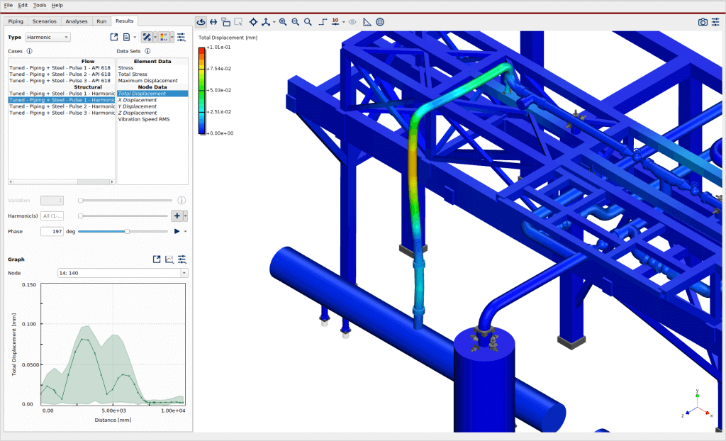
In a forced mechanical response analysis, in the acoustic simulation, calculated shaking forces are applied to the system using the ANSYS plugin in BOSpulse to evaluate the vibration levels and fluctuating stress levels.
During commissioning or after changes to the operating conditions, operational vibration levels may become critical because the Eigenfrequencies changed and moved closer to the excitation frequencies. In these situations, DRG supports its clients using a high pace vibration assessment, root cause analysis, and mitigation. A client-specific approach is proposed typically including vibration measurements and acoustic and mechanical simulations.
Conducting these in sync means DRG can quickly determine whether the system is safe to operate or at risk of failure with continued operation. The root cause, whether acoustic or mechanical, of the vibrations can also be resolved quickly. Finally, DRG can propose the most effective way to mitigate the vibrations based on the acoustic and mechanical simulations.
