In this study, the dividing wall of a vessel was subjected to a design pressure differential of 0.03 bar, while the shell had a design pressure of 8 barg. Under these conditions, it was highly probable that the dividing wall would experience deflection.
Analysis
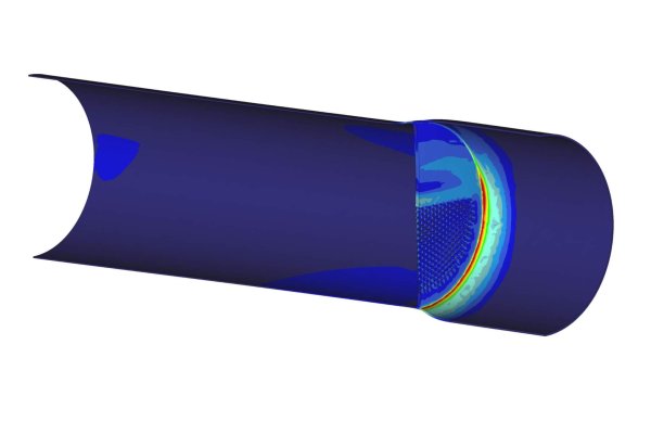
To evaluate the design under these conditions, several structural Finite Element (FE) calculations were performed using two different software packages: FEPipe and Pro-Engineer/Pro-Mechanic. This dual approach was employed to enhance the reliability of the results. Additionally, Femap was used to conduct a plastic analysis. Finite element models were created for the most critical sections of the vessel’s shell, the dividing wall, and all circumferential stiffeners.

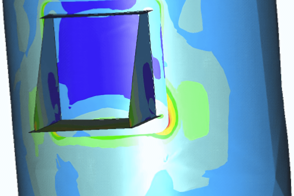
Preliminary calculations confirmed that the most critical sections were the areas of the dividing wall between large stiffener spacings. The maximum deflection of the divider plate occurred between two stiffener levels with the largest spacing. This deflection resulted from the counter-rotating effect between the deflected lateral stiffener on the dividing wall and the rotation caused by the outward deflection of the circumferential shell stiffener. The outward rotation of the stiffener was induced by the radial expansion of the shell due to internal pressure, which was constrained by the dividing wall.
The stiffener on the dividing plate caused an opposite rotation due to the pressure differential across the dividing plate. This interaction significantly influenced the deflection patterns observed.
Results
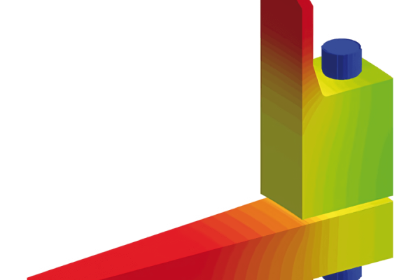
The analysis concluded that the optimal solution was to decouple the stiffeners on the shell from those on the dividing wall. By detaching the two stiffeners, cutting them back, and tapering their ends, the counter-rotating effect between the stiffeners was completely eliminated.
To prevent compromising the deflection of the dividing plate, the gaps between the dividing wall stiffeners at the middle levels were filled for odd tray supports. This adjustment ensured structural integrity and reduced deflection under the specified design conditions.