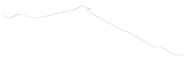
A 5-inch glass-reinforced epoxy (GRE) transportation line has been installed underground, featuring several above-ground steel pipe connections. Designed to withstand a pressure of 150 bar and tested up to 214 bar, the line operates under a steady temperature of 40°C, minimizing thermal impacts. Issues with original pipe elbows prompted the installation of custom-made large radius bends using 22.5-degree elbows. Notably, hydrotest conditions were carefully considered during this process.
Analysis
The transportation line faces significant stress, particularly at its above-ground connections and buried elbows, due to the high operational pressures. Originally, the hydrotest planned for the elbows did not include soil cover, enabling visual leak detection but also reducing soil resistance against pipe extension caused by hydrostatic pressure. This setup leads to notable stress concentrations in the elbows and adjoining straight pipe sections.
Stress Analysis
Conducted in accordance with the GRP piping standard ISO 14692 and utilizing CAESAR II pipe stress analysis software, the study includes modeling of the buried GRE pipe connected to above-ground steel components. A midpoint connection to an above-ground steel manifold is also integrated into the analysis model to ensure comprehensive boundary conditions. Special focus is placed on accurately modeling the non-standard large radius elbows using CAESAR II due to their critical nature.

Results
Analysis confirms that all stresses within the GRE piping meet operational limits set by ISO 14692. However, stress levels during hydrotest conditions exceed permissible values in the elbows. To address this, an analysis-derived table is developed outlining maximum allowable displacements for each elbow’s connected straight pipe segment.
“After encountering issues during the initial hydrotest, DRG established a revised testing protocol for a successful second test.”
Conclusions
During the gradual pressure increase of the in-field hydrotest, displacement measurements will be monitored against the specified table values. If displacements exceed permissible limits, strategic burial of the pipeline will enhance soil resistance, thereby limiting pipe extension. Notably, areas around elbows and their immediate adjacent straight pipe sections will remain uncovered to facilitate visual inspection, with the majority of the distant straight pipe section remaining exposed.
