Introduction
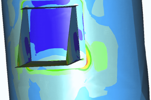
This study detailed the mechanical calculations for four internal components designed as gas inlet distributors within a pressure vessel. These internals were welded to the pressure vessel’s interior and further supported by H-beam constructions on each side. The “divider box” was a carbon steel structure made from welded plates, forming four separate flow ducts. The attached “vane type distributors” were fabricated from three stainless steel plates and stainless steel vanes.
During the operation, slug formation was expected, leading to significant forces due to momentum exchange. The primary objective of this study was to determine the resulting material stresses and recommend improvements if necessary.
Analysis
To understand the effects of slug loading on the internals, initial two-phase flow calculations were performed to predict the flow regimes based on the client’s provided process conditions. The flow theories of Baker, Hewitt, and Taitel were employed for this purpose.
Using the derived slug loads, stresses were calculated via finite element analysis (FEA) and manual computations. Additionally, the assembly was evaluated for potential instability.
Results
The calculations indicated that the curved mid-divider plate required support from a vertical plate at its center. Additionally, it was found that the four bolted flange connections were overloaded during slug conditions. These flanges were expected to deform plastically under slug impact, transferring the full dynamic load to the H-frames. This load transfer would then cause excessive primary stresses in the beams and the welds connecting the beams to the shell.
The phase velocities of the gas and liquid were determined using Lockard and Martinelli’s approach.
To address these issues, a bolted lap joint connection with minimal clearance bolts was suggested for attaching the divider plate to the distributor plate. Ensuring minimal tolerance between bolts and bolt holes was critical to reduce load transfer to the frame.


