Introduction
In this case study, a burst test was conducted to demonstrate the strength of a DN1200 Glass Fiber Reinforced Plastic (GRP) pipe. The objective was to ensure that the pipe spool could endure an internal pressure six times greater than the design pressure of 10 Barg, equivalent to 60 Barg for a short duration.
To facilitate the test, the spool was laminated to two GRP flanges and sealed with two steel-reinforced blind plates. The engineering of the GRP flanges, reinforced blind plates, and bolts was critical to ensure they were stronger than the test spool. The goals were twofold:
- Confirm that the GRP spool can withstand at least a short-term pressure of 60 Barg.
- Determine the maximum pressure the GRP spool could endure.
FE Model Setup
The flange and bolt assembly was modeled using a rotationally symmetric finite element (FE) model that represented a single bolt, relying on periodic symmetry for the other bolts. The model incorporated non-linear restraints for the bolt-to-nut threads, nut-to-ring surfaces, and gasket to simulate lift-off effects, which represent the loss of load-carrying capability.
For the steel blind plate, a 3D FE model with solid elements was created. This model included the bolts to accurately determine the clamp stiffness and calculate the correct bending stress within the plate.

Results
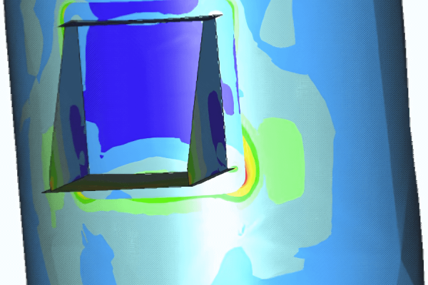
The analysis revealed that shear stresses in the GRP flange were a significant concern. Modifying the general layout of the flange was not an option, as it needed to remain consistent. The compressive force from the steel backing ring resting on the GRP flange induced shear stresses that could lead to inter-laminar delamination and potential failure of the flange.
It was concluded that FE analysis is effective for modeling anisotropic materials like GRP. To enhance the flange strength while maintaining its layout, changes in the laminate build-up of the flange were suggested. These modifications showed that the flange would survive the burst test, with a limit pressure slightly over 60 Barg.
Additionally, the initial design of the steel blind flange proposed by the client had to be altered. The FE analysis indicated that the original design resulted in stresses exceeding the allowable material stress limits, necessitating a redesign to ensure safety and performance.


