Vibrations Analysis – Induced Vibrations
Brief introduction to piping vibrations
Vibrations are an oscillatory motion about an equilibrium. The oscillatory movement causes alternating stresses in the system, which, if excessive could lead to fatigue failure.
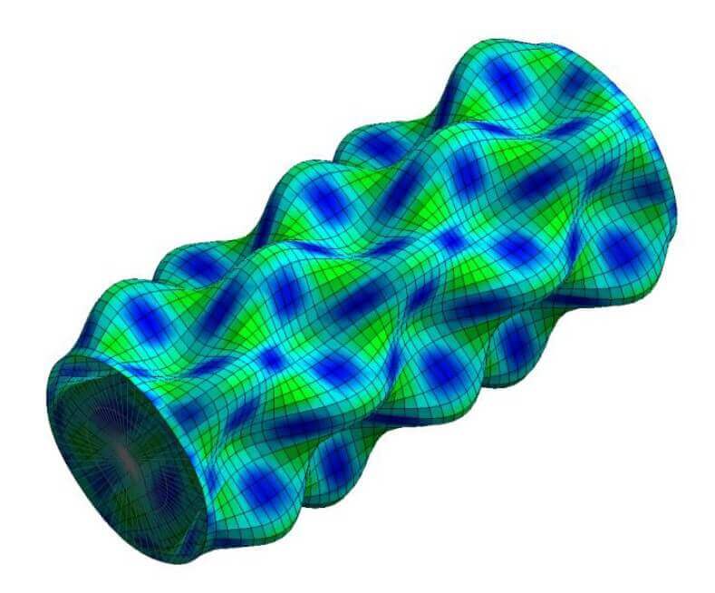
Every structural system will exhibit a series of natural frequencies: the frequencies at which the system can easily vibrate. Natural frequencies depend on the system stiffness and mass distribution, where stiffer structures vibrate at higher frequencies. Each natural frequency will have a unique deflection shape associated with it, called the modal response. Without the presence of an excitation source, a system will not vibrate.
Resonance occurs when the frequency of excitation and the natural frequency of the system align. At resonance, all excitation energy can be used to drive the natural frequency of the system. This leads to the largest vibrations.
High vibration amplitudes in a system however are not necessarily related to resonance. If the excitation source is strong enough, excessive vibrations can still be caused in the structure, even though the natural frequencies of the system are not matched. The vibration levels are generally lower than in the resonant case though.
There are different sources of excitation that can cause a piping system to vibrate. Some of these sources excite the system at specific frequencies, while others are so-called broadband excitation sources. The method of mitigation is different depending on the source of excitation. The sections below give details on a few common, process-related, excitation sources.
Types of Induced vibrations
Acoustic Induced Vibrations
Description
Acoustic Induced Vibrations (AIV) are vibrations that can be excited in gas systems with large pressure drops over a device. The vibrations will be excited downstream of such a device. Examples of devices with large pressure drops are Pressure Safety Valves (PSVs), blowdown valves, pressure reducing valves, control valves and restricting orifices. AIV produces high-frequency, broadband excitation, typically between 500 and 2000 Hz. Due to the high frequency of the vibrations, the number of cycles a system experiences is large and therefore the time to failure can be very short (could be in the order of minutes). Fatigue caused by AIV is of particular concern as it tends to affect safety related systems.
The internal acoustic energy of AIV produces high tonal noise that could pose a risk for operator safety (hearing loss).
AIV fatigue failure primarily occurs in nearby welds, downstream of the pressure-reducing device. Locations where failure might occur include welded supports, welded branch connections, and welded fittings. Small-bore connections are the most critical. The broadband excitation means there will be overlap with some structural mode(s), of cracking and fatigue failure.
Solution Approach
An AIV study always starts with the calculation of the sound power level (PWL) and the assessment of the system’s resistance to fatigue failure. Mitigation measures, when applicable, are related to reducing the PWL, reinforcing the critical parts of the system, or moving the critical parts further away from the excitation source. By moving critical parts, often small bore connections, further away from the source of AIV, the PWL will have attenuated to a lower intensity.
There are two approaches for evaluating AIV:
- Eisinger method
- Energy Institute Guidelines
Both methods calculate the sound power level (PWL) in a similar way. DRG can help to evaluate a newly designed system by identifying AIV sources and high-risk areas. DRG can propose mitigation measures aimed at reducing the dynamic stress levels, if necessary.
Flow Induced Vibrations (FIV)
Description
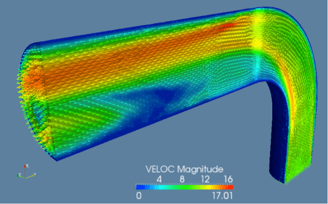
Flow Induced Vibrations (FIV) / Flow Induced Turbulence (FIT) refer to vibrations that occur due to high kinetic energy resulting from turbulent mixing with boundary layer separation. The vibrations due to FIV typically occur in a broad frequency range, with excitations between 1 and 100 Hz. Major flow discontinuities like bends, tees, partially closed valves and small-bore connections are particularly susceptible to turbulent flow and flow induced vibrations. Systems with high flow rates are also more at risk of experiencing FIV. There are some FIV related excitation sources, such as flow in a header along a dead-end branch, that produce vibrations at distinct frequencies, rather than broad-band excitations.
These vibrations can cause fatigue failure in the system after continued operation. While it is best to eliminate vibration issues in the design phase, FIV related issues can also be mitigated during operation when identified during start-up/commissioning.
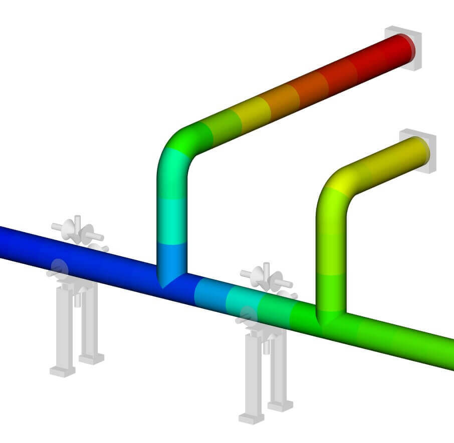
Systems that are especially susceptible to FIV are gas, multi-phase, or liquid systems with high flow velocity. Piping systems supported on racks or other elevated structures are also more susceptible to FIV related issues.
Solution Approach
DRG can help with screening systems for possible locations where FIV could occur. When high-risk locations are identified, DRG can determine the extent of the risk and propose mitigation measures. These mitigation measures may be related to reducing the excitation, by changing the flow conditions, or damping of the vibrations in the system. It is also possible to change the stiffness of the support layout, to move the natural frequency away from the excitation frequency and resonance. Computational Fluid Dynamics can be used to quantify flow-induced vibrations when a more detailed analysis is required.
Flow Induced Pulsations
Description
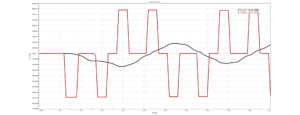
Flow Induced Pulsations can cause excessive vibrations and fatigue failure in piping systems. The pulsations arise due to the coupling of vortex shedding (typically from a dead-end side branch) with acoustic resonance modes in the system. If the acoustic mode in the side branch is excited by the vortex shedding a standing pressure wave (pulsation) can form in the dead-end branch.
The frequency of this standing wave causes oscillating pressure differences in the piping of the side branch. These can lead to unbalanced shaking forces and vibrations.
The worst-case scenario would be if the structural natural frequency is close to the frequency of this pulsation. Pulsations are beam-type vibrations and can cause fatigue failure in the system after continued operation. While it is best to eliminate the issues during the design phase, Flow-Induced Pulsation issues can also be mitigated during operation when identified during start-up/commissioning.
Systems that are especially susceptible to Flow Induced Pulsations are gas systems with high flow velocity together with equal diameter/relatively long dead-end side branches.
Solution Approach
The favorable solution would be to remove the source of the pulsations. This can be achieved by changing the flow characteristics at the location of the branch connection, or by detuning the acoustic resonance frequency to prevent the standing pulsation wave from forming.
Vortex Induced Vibrations
Description
External flow over a cylindrical shape may give rise to vortex-induced vibration. A pipe, a chimney, or the vertical pole of a wind turbine exposed to wind can develop vortex-induced vibration. Cylindrical equipment that protrudes into the flow, such as thermowells, within a pipe or a heat exchanger tube array subjected to the flow of the process fluid, can also give rise to vortex-induced vibrations.
Based on the fluid velocity, the diameter of the cylindrical shape subjected to the flow, and the Strouhal number, the excitation frequency of the vortices in the fluid or gas is determined. When this frequency lies close to the natural frequency of the cylindrical structure, frequency locking will result in dangerous resonance of the structure or pipe, with only very limited structural damping.

Solution Approach
DRG has developed tools to analyze cylindrical structures or equipment subjected to external flow. Depending on the flow conditions, the vortex shedding frequency will be determined. The vortex shedding frequency depends on the velocity of the fluid around the object. The largest vibrations are observed when the vortex shedding frequency matches the structural natural frequency. It should be noted here that higher flow velocity doesn’t always represent the worst case when it comes to vortex-induced vibrations.
Based on the natural frequency of the structure or equipment, mitigation measures can be taken. In the case of chimneys, vortex breakers can be added to the outside of the cylinder to break the symmetry of the cylinder and prevent vortices from forming in the flow.
Vibrations Caused By Pulsating Flow
Description
Other sources of vibrations exist such as pulsating flow caused by reciprocating equipment such as pumps or compressors. DRG has years of experience in pulsation analysis according to API-618 for compressor systems and API-674 for pump systems. Find out more about our pulsation analyses here.
Conclusion
Dynaflow Research Group can provide engineering consultancy services with these vibration issues. We have expertise in Flow Analysis, CFD, Vibration analysis, and (Dynamic) Stress Analysis and can therefore provide full support with any type of vibration issue.
At DRG, we have developed the BOSpulse software package to perform pulsation analyses. This package enables engineers to perform an acoustic analysis of the system, which can help with analyzing vibration-related problems.
Author: Thijs Krijger, Senior Engineer
Resources
Further Reading
Training Available
Learn more about our vibration analysis services :
Get in touch with one of our team members

Related Articles
Surge Awareness In Firewater Systems
As part of our responsibilities at DRG, we conduct both standard pressure drop calculations and surge/slug analyses for firewater systems. Our involvement spans various stages,
Well Integrity For Fiberglass-Casing Based Well Design
Geothermal energy is a promising renewable energy source, but it comes with its own set of challenges. Two significant issues in geothermal well operations are
Understanding Flow-Induced Vibrations in Piping Systems
Flow-induced vibrations in piping systems are a critical aspect of mechanical engineering, impacting the reliability and integrity of various industrial setups. The Japan Society of