Thermal bowing is a structural phenomenon that arises when a temperature gradient exists across the cross-section of a pipe or vessel. In typical pipe design, uniform heating results in straightforward, predictable thermal expansion, managed through design features such as expansion loops or joints. However, when one part of a pipe’s cross-section (such as the top) is hotter than another (like the bottom), the material attempts to expand at different rates along the cross-section. Since the material cannot physically separate, this uneven expansion results in the pipe curving—an effect known as thermal bowing. The pipe may “hog” (arch upwards) if the top is hotter, or “sag” (bend downwards) if the bottom is hotter. This curvature generates additional bending moments and can introduce significant stress into piping systems, affecting both their integrity and their supports.
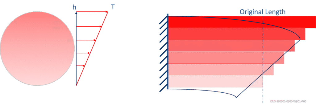
The mechanics of thermal bowing are similar to those seen in a bimetallic strip, where two metals with different expansion coefficients bend when heated unevenly. In pipes, the effect is induced by a temperature gradient, not by material differences. The curvature created is proportional to the temperature difference, the coefficient of thermal expansion, and inversely proportional to the pipe diameter.
Origin & Impact of Thermal Bowing
Thermal bowing most commonly occurs in scenarios where a cross-sectional temperature gradient can develop. This is particularly relevant in:
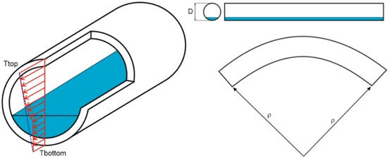
- Partially filled lines (such as LNG, LPG, or steam lines), where the liquid portion has a higher heat transfer coefficient than the vapor portion, resulting in uneven heating of the pipe wall.
- Uninsulated pipes exposed to sunlight, where the sunlit side becomes significantly hotter than the shaded side.
- Pipes with stratified or stagnant flow, where heat transfer varies around the pipe’s circumference.
The impacts of thermal bowing can be significant and, if not addressed early in the design or analysis phase, may lead to operational issues. The induced curvature can cause unexpected additional bending moments in the pipe, potentially overloading supports or even causing some supports to lose contact (lift-off). This redistribution of support loads can increase localized stresses, leading to accelerated wear, failure of support structures, compromised pipe integrity, or even catastrophic failure in extreme cases. In complex assemblies—such as stacked vessels—thermal bowing can cause large displacement differentials between supports, increasing the difficulty of maintaining proper alignment and load sharing.
Understanding, Modelling, and Managing Thermal Bowing using CAESAR II
Thermal Bowing in CAESAR II
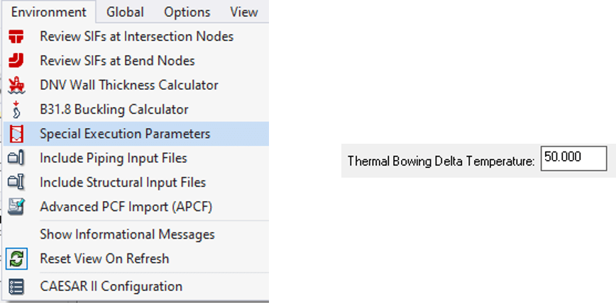
Industry-standard piping analysis software, such as CAESAR II, has dedicated features for modeling thermal bowing effects. This capability is accessed through the software’s special execution parameters, where users specify the “thermal bowing delta temperature”—the temperature difference between the top and bottom of the pipe section. A positive value simulates hogging (top hotter), while a negative value simulates sagging (bottom hotter).
CAESAR II automatically calculates the resulting bending moment using the specified temperature difference, the elastic modulus, moment of inertia, and the thermal expansion coefficient (which itself is temperature-dependent and referenced to the pipe’s centerline temperature). This bending moment is then incorporated into all relevant temperature load cases.
The software makes several key assumptions: the thermal strain distribution is linear across the cross-section, bowing is only applied to horizontal pipes within a user-defined pitch tolerance, and the effect is modeled only in the vertical plane. The default horizontal tolerance is 0.0001—any pipe with a pitch less than this value is considered horizontal and subjected to bowing loads. These assumptions should be considered when interpreting results and designing mitigations.
Simple Line Example of Thermal Bowing in CAESAR II
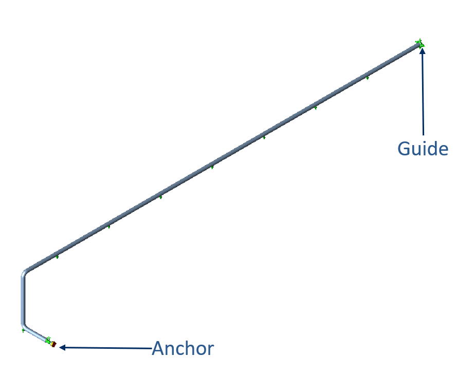
To illustrate the significance of thermal bowing, consider a simple straight run of 12-inch (273.05mm OD) SA106 Gr.B pipe, Schedule 20, operating at 75°C and 20 bar, with a 50°C temperature difference between the top and bottom. The model includes an anchor at one end, a rest/guide/hold-down at the other, and a trunnion support beneath a vertical elbow.
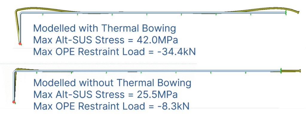
When thermal bowing is not included in the analysis, the pipe exhibits standard vertical expansion and all supports remain active. The highest restraint load is 8.3kN, and the maximum sustained stress reaches 18.5% of the code allowable.
Activating thermal bowing (with a +50°C delta) drastically alters the system’s response. The pipe develops a pronounced hogging profile, with much greater vertical movement. Notably, three supports lift off, the maximum restraint load jumps to 34.4kN, and the maximum sustained stress increases to 30.4% of the code allowable. Critically, the location of the highest stress also shifts within the system.
This example underscores the importance of using appropriate load cases in CAESAR II (such as Alt-Sustained) to capture the real effects of support lift-off and redistribution of loads. Failing to account for thermal bowing can lead to a substantial underestimation of system stresses and support reactions, putting the integrity of the system at risk.
Understanding, Modelling, and Managing Thermal Bowing using CAESAR II
Example of Thermal Bowing on a Stacked Vessel
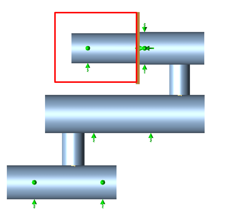
Thermal bowing also impacts larger, more complex equipment, such as stacked horizontal vessels. Consider a three-tiered vessel assembly, each vessel constructed from SA516 Gr.70 (2200–2800mm OD, 28–36mm thick), operating at 200°C with a 50°C temperature gradient between the top and bottom of each tier. The assembly is supported at six points and includes a heat exchanger at the top, with a tubesheet that isolates one side from the bowing effect.
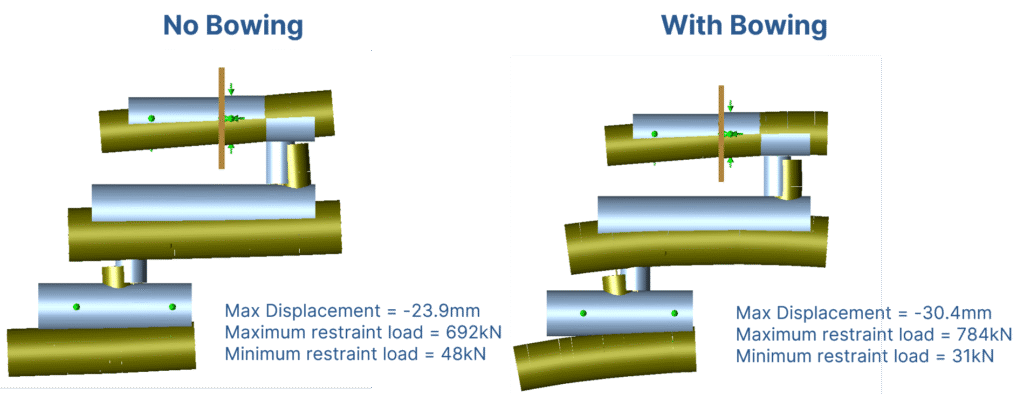
When modeled without thermal bowing, the vessel stack displays typical downward displacement due to weight, with a maximum displacement of 22.8mm and a maximum restraint load of 668kN (compared to a minimum of 63kN). Introducing thermal bowing increases the maximum displacement to 29.8mm and the maximum restraint load to 770kN, while the minimum restraint load drops to 49kN—widening the disparity among support reactions. This larger load disparity can complicate support design and compromise stability.
To address this, the model was updated to use flexible spring supports on the lower tiers, with optimized spring rates to distribute the loads more evenly. This adjustment reduced the maximum restraint load to 568kN and raised the minimum to 107kN, significantly narrowing the load disparity and improving the system’s response.
While the overall bowing is still present, the even distribution of support reactions mitigates many of the negative impacts, such as excessive tilt or uneven settlement. Communicating these displacement figures to pipe vendors and contractors is critical to ensure that connecting systems can accommodate the observed movement.
Thermal Bowing Mitigation Measures
Managing thermal bowing involves strategies that address both the source of the temperature gradient and the structural response of the system.
Mitigation against the source focuses on eliminating or minimizing the temperature differential across the pipe or vessel cross-section. This can be achieved by ensuring uniform heating—using full 360° insulation, applying heat tracing to maintain even temperatures, or managing flow to avoid partial fill or stratification. For outdoor piping, insulation is especially effective at negating temperature gradients caused by sunlight.
When complete elimination of temperature gradients is impractical, mitigation focuses on accommodating the effects. This includes using flexible or spring supports to absorb the additional movements induced by bowing, optimizing support locations and stiffness, and designing piping layouts to enhance flexibility and avoid long, unsupported horizontal runs. Proper communication of expected displacements and support loads to contractors and equipment vendors is also essential to ensure compatibility throughout the connected systems.
In summary, thermal bowing is a critical consideration in the design and analysis of piping and vessel systems, particularly where temperature gradients are likely. CAESAR II provides robust tools for modeling these effects, but engineers must apply them with a clear understanding of the underlying mechanics and system-specific impacts. Through proper analysis, design, and mitigation, the risks posed by thermal bowing can be managed, maintaining the safety and integrity of vital process infrastructure.