In 2013, a major incident occurred in a Louisiana chemical plant. In a nonroutine operation, plant operators attempted to start a heat exchanger which had been inactive for some time. Unbeknownst to the operators, the heat exchanger shell side was filled with liquid and was closed off from its pressure relief by a closed valve. As this entrapped volume of liquid began absorbing heat in the exchanger, the pressure in the loop started rising far above the nominal operating pressure as a result of hydraulic thermal expansion.
Eventually, extreme pressures caused a rupture in the heat exchanger shell, leading to an explosion and subsequent fire. While the investigation found that poor safety management was to blame, the physical process responsible for the incident was the thermal expansion of the shell-side heat exchanger liquid in a closed volume. This is just one example of the dangers that hydraulic thermal expansion can pose if the associated risks are not mitigated.
Liquid block-in for extended periods should not occur during normal operation of a system, as the system and operating procedures can be designed to prevent this. Trapped liquids are most common during maintenance, emergencies, or other nonroutine operations. During the maintenance of a system, manual safety valves may be closed which would normally remain open. Additionally, in a power loss event, some electronically actuated valves may return to their unpowered state. This often puts the system into a safe state but may have the unintended effect of creating sections of trapped liquid if not done carefully.
To give an idea of the pressures that may arise due to thermal expansion, trapping water in a 1″ standard schedule steel pipe at 10 °C and heating it to 30 °C will cause an increase in pressure of nearly 50 bar. A crucial distinction must be made between fully liquid-filled systems and gas-liquid systems. While the former often shows a dramatic increase in pressure as the temperature rises, the latter can have a sufficient amount of vapor present to effectively cushion the thermal expansion of the liquid. It must be kept in mind however that even a seemingly large gas volume fraction of 10% may not be enough to prevent a large build-up of pressure if the temperature increase is large enough, and if the liquid has a large thermal expansion coefficient as is the case for ammonia for example.
Dealing with hydraulic thermal expansion
In systems where overpressure is a possibility, Pressure Relief Valves (PRVs) are often used to ensure that the pressure in the system does not exceed the maximum allowable working pressure. PRVs open automatically when a certain limit pressure is reached (usually via a spring mechanism), thereby preventing dangerous pressures from building in the system. Since PRVs do not require human intervention, they are among the most reliable overpressure safety devices. Thermal Relief Valves (TRVs) operate in the same way as PRVs and protect the system against overpressure. The main difference is that TRVs usually allow for a smaller volumetric flow since a pressurized liquid-filled system requires only a few drops of liquid to be expelled to bring the pressure down to acceptable levels. In comparison, a system filled with highly pressurized gas will need to relieve a significant amount of volume to achieve the same pressure reduction, due to the high compressibility of gas compared to liquids.
Modeling hydraulic thermal expansion
While standards exist to determine whether Thermal Relief Valves are required in a system (such as ISO 23251) to protect the equipment and the system, they often leave room for the designer’s interpretation. It can therefore be a useful exercise to determine the pressure rise as a result of the thermal expansion of a trapped liquid, as this provides insight into the behavior of the system and allows for a deeper understanding of factors determining the pressure rise.
As a first estimate of the pressure rise due to thermal expansion, one may assume the volume in which the liquid is trapped (this can be piping, valves, flanges, or pressure vessels) to be perfectly rigid. The final internal pressure for a given increase in temperature then follows from a simple balance between the volume change of the liquid due to thermal expansion, and the volume change of the liquid due to the pressure applied to the fluid, by the infinitely rigid container. This provides an absolute upper bound on the pressure rise, as in reality, the system will start deforming as the internal pressure rises, which provides a pressure-relieving effect.
The level of detail of the calculations can now be increased stepwise. The ISO 23251 standard provides equations to determine the pressure rise in a blocked-in, liquid-filled pipe section, while also incorporating the increase of available internal volume due to thermal expansion of the pipe material, and elastic deformation of the pipe due to the internal pressure. For long pipe sections this result may already be detailed enough, but for shorter pipe sections where liquid may become trapped between large flanges, deformation of the flanges can provide significant additional volume for the liquid to expand in.
Depending on flange geometry, a flanged connection can provide a pressure-relieving effect for a thermally expanding trapped liquid. Under high pressures, the flanges will start to rotate, making additional internal volume available and in the process allowing the liquid to expand more. This effect can be seen in (Figure 1), which shows the exaggerated deformation of a standard PN25 DN250 flange subject to internal pressure. The flange will bend around its bolts, increasing the internal volume leading to a pressure-relieving effect, but leading to high stress concentrations in the bolts and flange necks and a decrease of gasket pressure which may result in leaks.
An interesting observation here is the fact that for a given pressure, a flanged connection will provide a constant increase in internal volume, regardless of the length of the attached piping. This leads to the counterintuitive effect where for a spool section with flanged connections, increasing the length of the spool will lead to higher pressures as a result of thermal expansion of the trapped liquid inside.
This is because a longer spool will have more trapped liquid that expands. The contributions to volume increase due to the elastic deformation of the spool itself scale linearly with the spool’s length. The contribution from the bending of the flanges however will be constant, so its relative contribution to pressure reduction will decrease as the spool is lengthened.
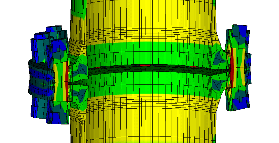
Figure 1: Exaggerated deformation and stresses in a standard PN25 DN250 flange subject to internal pressure
Heat transfer and liquid properties
The rate at which the fluid heats up can be valuable to know, especially if a liquid is expected to be trapped for short times only, and overpressure is prevented by the timely opening of valves. This introduces heat transfer to the problem. The thermal and mechanical effects are considered to be decoupled and therefore the thermal problem and mechanical problem can be solved separately instead of simultaneously, simplifying the problem.
In addition to the mechanical properties of the system, the thermodynamic and chemical properties of the potentially trapped liquid can play a major role, both in terms of probability and severity of the risks. Perhaps the most relevant property of the liquid here is the thermal expansion coefficient. For water at room temperature, this value is equal to 2.1E-4, which means that when heating one liter of water by one degree, its volume will grow by 0.21 milliliters. Liquid ammonia, which is not uncommon in chemical installations, has a thermal expansion coefficient more than 10 times that, at around 2.3E-3. This means that for a temperature increase of just 20 degrees, the volume of ammonia will rise by almost 5%! When cryogenic liquids are used, one must exercise even more caution in preventing trapped liquids. This is due to the high-temperature difference between the cryogenic liquid and ambient conditions, which leads to faster heating than normal.
To take all of the thermal expansion effects mentioned above into account and achieve the highest level of detail, a finite element analysis can be performed. While this requires more effort to set up and large computational resources to run, an FEA study will be able to give the greatest insight into the stresses in the system as a result of hydraulic thermal expansion. Additionally, if a thermal-mechanical coupled FEA study is performed, the transient behavior of the system can be found which will aid the process of identifying and mitigating hydraulic thermal expansion risks.
Pressure reducing leakage
One aspect which has not yet been mentioned is the possibility of leaks in the system. Ideally, a system would not leak at all, but in the case of thermal expansion, some controlled leakage at higher pressures can be beneficial in relieving the built-up pressure and preventing more severe failure modes. Depending on the internal volume of the trapped liquid, often a tiny amount of leakage will considerably decrease the pressure due to the near-incompressibility of liquids. Still, especially when working with hazardous liquids, knowing how much is leaking, and where, can be crucial.
Leakage may occur through the flange connection. A reduction in gasket pressure will eventually reduce the gasket pressure to values below its minimum required pressure to maintain a leak-tight connection. Internal leakage may occur due to the bending of valve internals. An example of this is shown in Figure 2, where excessive pressure on a butterfly valve disk causes bending that creates a leak path for trapped liquids.
If the analysis finds that pressure-reducing factors such as flange bending and internal/external leakage are insufficient, the risks posed by hydraulic thermal expansion must be mitigated by other means. This can be done by enforcing stringent operating procedures, which ensure that liquid does not become trapped in a closed system at any point. This leaves safety fully in the operator’s hands, allowing room for human error. Active overpressure protection by means of thermal relief valves is inherently the safest option.
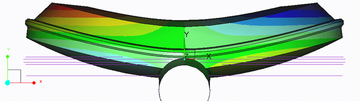
Figure 2: Top view of exaggerated deformation of a butterfly valve disk
Share this article
Get in touch with one of our team members

Related News & Insights
Surge Awareness In Firewater Systems
As part of our responsibilities at DRG, we conduct both standard pressure drop calculations and surge/slug analyses for firewater systems. Our involvement spans various stages,
Well Integrity For Fiberglass-Casing Based Well Design
Geothermal energy is a promising renewable energy source, but it comes with its own set of challenges. Two significant issues in geothermal well operations are
Understanding Flow-Induced Vibrations in Piping Systems
Flow-induced vibrations in piping systems are a critical aspect of mechanical engineering, impacting the reliability and integrity of various industrial setups. The Japan Society of