Table of Contents
As the demand for flexible, energy-efficient, and reliable compressor operation grows—particularly in hydrogen and process gas applications—our clients increasingly turn to stepless capacity control for reciprocating compressors.
Stepless capacity control, implemented via suction valve unloading, enables precise, continuous adjustment of compressor output. This approach is a significant advancement over traditional stepwise or bypass methods, offering optimized energy consumption, improved process stability, and reduced mechanical wear. Our experience shows that stepless control not only meets the stringent requirements of modern process industries but also ensures compliance with the latest API 618 and API 688 standards. In this article, we share our technical insights and best practices for understanding, analyzing, and modeling stepless capacity control, drawing on our field experience and proprietary BOSpulse software.
Compression – PV Diagram
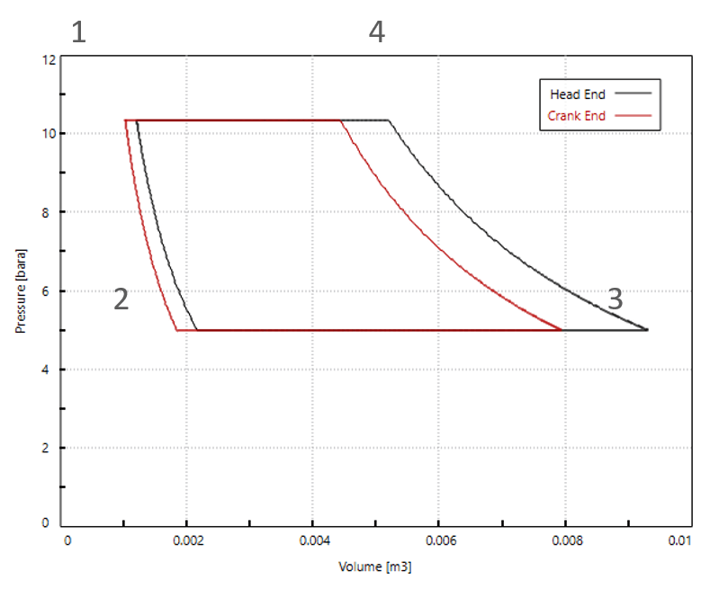
A fundamental understanding of reciprocating compressor operation begins with the Pressure-Volume (PV) diagram. Under normal operation, the compressor displaces a fixed volume per stroke, following a cycle:
- 1–2: Both suction and discharge valves are closed; the piston compresses the gas, increasing pressure as volume decreases.
- 2–3: The suction valve opens, allowing gas to enter as the piston moves down; pressure remains near the suction line.
- 3–4: Both valves are closed again; the piston compresses the gas until the pressure exceeds the discharge line.
- 4–1: The discharge valve opens, and compressed gas is expelled.
The area within the PV diagram represents the work performed by the compressor during each cycle.

How Stepless Capacity Control Shapes Flow and Pulsations
PV-Diagram Changes Under Suction Valve Unloading
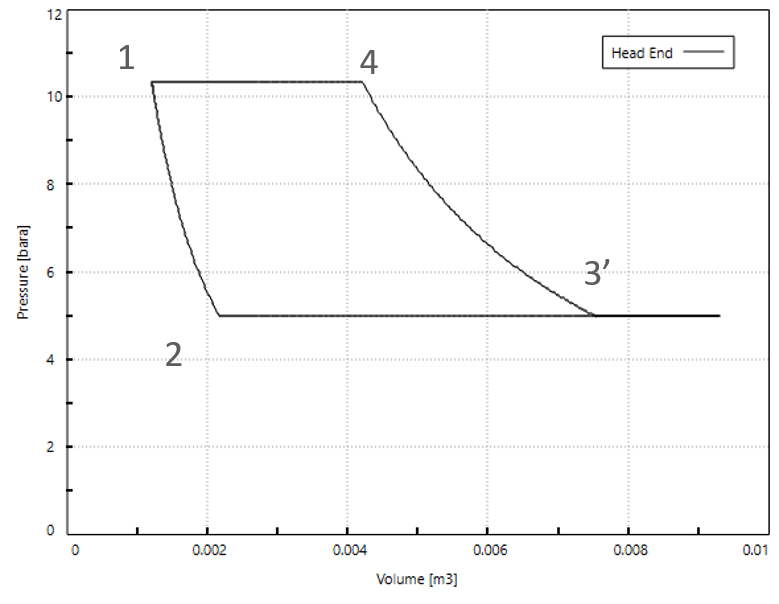
Stepless capacity control fundamentally alters the PV diagram by modifying the suction valve timing:
- 1–2: Both valves closed, compression begins.
- 2–3: Suction valve opens, gas enters the cylinder.
- 3–3’: The suction valve is held open longer into the compression stroke, allowing some gas to flow back into the suction side—delaying compression.
- 3’–4: The suction valve closes, and compression resumes until the discharge valve opens.
- 4–1: Discharge valve opens, gas is expelled.
This introduces a “flat” segment in the PV diagram (3–3’), where pressure remains constant while volume decreases, representing the period of reverse flow. The result is a smooth, stepless reduction in compressor capacity, without the energy losses associated with bypass or on/off control.
Flow Profile of Compressor
In standard operation, the flow profiles through the suction and discharge valves are periodic and closely follow the piston’s movement:
- Suction Valve: Opens during the intake stroke, with flow peaking as piston speed is highest.
- Discharge Valve: Opens during the compression stroke, with flow peaking as the discharge valve opens.
These profiles are generally symmetric and repeat with each crankshaft revolution, providing a predictable flow pattern.


Flow Profile of Compressor with Valve Unloading
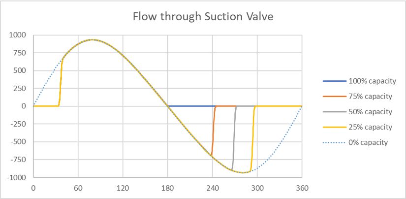
With stepless capacity control, the flow profiles change significantly:
- Suction Valve: Remains open longer into the compression stroke, resulting in a period of reverse flow—gas flows back from the cylinder into the suction line. The flow profile now includes a negative segment, the magnitude and duration of which increase with the degree of unloading.
- Discharge Valve: The net flow through the discharge valve decreases as less gas is compressed and expelled. At full unloading, discharge flow can approach zero.
At intermediate capacities (e.g., 25%, 50%, 75%), the flow profiles show a mix of forward and reverse flows through the suction valve, and the discharge flow peaks become smaller and narrower. These changes are critical for understanding the impact of stepless capacity control on system dynamics and pulsation behavior.

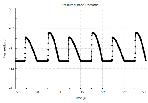
Flow Pulsations Proportional to Pressure Pulsations
In reciprocating compressors, the periodic piston movement generates flow pulsations, which are directly proportional to pressure pulsations. Each compression and suction event creates a pressure wave that propagates through the piping system. The magnitude of these pulsations depends on the compressor’s displacement, speed, and gas properties.

How Stepless Capacity Control Shapes Flow and Pulsations
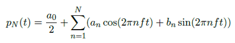
Pulsations in the Frequency Domain
At Dynaflow, we use frequency domain analysis—specifically the Discrete Fourier Transform (DFT)—to decompose time-domain pressure signals into their constituent harmonics. The base frequency corresponds to the compressor’s running speed, with higher harmonics as integer multiples. In double-acting compressors, the second harmonic often dominates.

Pulsations Propagate According to the Wave Equation
Overlap Between Excitation (Reciprocating Harmonics) and Acoustic Frequencies
A critical risk in compressor system design is resonance. If the excitation frequency (or its harmonics) from the compressor matches the acoustic natural frequency of the piping system, standing waves can form, dramatically amplifying pulsation amplitudes. The resonance frequency is determined by the wave speed and the length of the piping system, with formulas differing for open-closed and open-open boundary conditions.
API Conformance on Pulsation Levels
Reciprocating compressor systems are typically designed to meet:
- API 618 (6th Edition, 2024): Specifies allowable pulsation levels and analysis requirements for reciprocating compressors in petroleum, chemical, and gas industries. Section 7.11 details pulsation and vibration control, with formulas for allowable pulsation levels based on system parameters.
- API 688 (2nd Edition, 2023): Provides additional guidance for pulsation and vibration control, especially for systems with stepless capacity control. Annex B.2 recommends analyzing at least four capacity steps (20%, 50%, 75%, 100%) across the entire flow control range.
Other Considerations for Pulsation Studies
- Higher Harmonics: Stepless capacity control can increase excitation at higher harmonics, which may lead to excessive pulsations if not properly managed.
- Temperature Effects: Valve unloading can change gas temperature, affecting wave speed and, consequently, the acoustic response of the system.
- Orifice Sizing: Devices sized for high flow may not perform effectively at low flow, complicating pulsation suppression at reduced capacities.
How to Model Capacity Control in BOSpulse
At Dynaflow, we have developed BOSpulse, a specialized software tool for modeling and analyzing pulsations in reciprocating compressor systems, particularly under the variable conditions introduced by stepless capacity control:
- Simulation of Suction Valve Unloading: BOSpulse models the effects of extended suction valve opening, including reverse flow and changes in pressure and flow profiles.
- Frequency Domain Analysis: The software uses DFT to identify harmonic frequencies and assess the risk of resonance.
- Wave Propagation: BOSpulse incorporates the wave equation to simulate how pressure pulsations travel through the piping network, accounting for changes in gas properties and temperature.
- API Compliance: The tool enables analysis at multiple capacity steps (e.g., 20%, 50%, 75%, 100%) as recommended by API 688, ensuring that pulsation levels remain within allowable limits across the entire operating range.
By providing detailed insights into system behavior, BOSpulse supports optimized design, risk mitigation, and regulatory compliance.
Conclusions
Stepless capacity control represents a significant advancement in reciprocating compressor technology, offering unmatched flexibility, energy efficiency, and process stability. However, its implementation introduces new challenges in pulsation management and system analysis. At Dynaflow, our expertise, field experience, and advanced tools like BOSpulse ensure that our clients achieve safe, reliable, and efficient compressor operation across a wide range of applications and operating conditions. As industries continue to demand greater tunability and performance, stepless capacity control will play an increasingly vital role in the future of compressor system design.
For further guidance or support with your compressor systems, contact Dynaflow Research Group—your partner in advanced engineering solutions.