Fluid Flow
Two-Phase Flow Analysis of Fuel Jetty Terminal
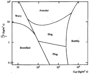
A fuel jetty terminal operator expressed concerns about potential two-phase flow issues during off-loading operations. The client indicated that trapped nitrogen used for purging lines

A fuel jetty terminal operator expressed concerns about potential two-phase flow issues during off-loading operations. The client indicated that trapped nitrogen used for purging lines

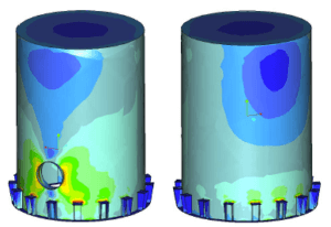
This case study introduces the stress assessment of two caissons: a sea water dump caisson with a 1000mm diameter header to which seven smaller diameter

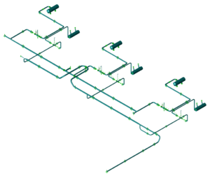
In this case study, a number of critical sections in an already installed fire water system were selected for review. At the time of the

An unloading line was being commissioned for use with cyclohexane. This line featured two ship loading arms located at the end of a jetty, and

This case study describes the stress analysis performed on a firewater piping system located in the Middle East. The system was constructed using Glassfier Reinforced
During a certain period, scaffolding was required around three 30m tall depropanizer columns. Since the scaffolding was laterally supported from the columns, all wind loads

Introduction At a Flow Station in Nigeria, vibration issues were observed in the suction and discharge headers, as well as the pump recirculation line. To

Introduction This study presents the findings from a comprehensive stability and stress analysis conducted on a planned high scaffolding construction surrounding a 30-meter-high column. The

Introduction A detailed pulsation analysis was conducted to evaluate the sensitivity of a new Measurement Proving Facility to disturbances. This facility, a piping installation designed

Computational Fluid Dynamics Analysis In this case study, we conducted a comprehensive analysis of the water flow in a pipeline featuring a 20-inch butterfly valve.

Surge And Dynamic Stress Analysis During the construction of a 1.6 km long steel pipeline intended for the offloading of naphtha from ships at a
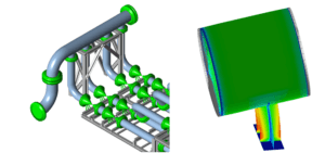
Introduction In this case study, we examine the static stress analysis performed on eight metering skids designed for a flow station. These skids, intended for

This case study discusses the results of a stress analysis conducted on the external section of the pressure equalizing piping at a reactor. The analysis

In this study, the dividing wall of a vessel was subjected to a design pressure differential of 0.03 bar, while the shell had a design

This study presents the results of a static stress analysis conducted on a compressor and the exit area of a compression station. Analysis A static

Introduction This case study recounts the stress analysis conducted for the design of two structural platforms attached to reinforcement rings on a vacuum tower. These

Introduction This study detailed the mechanical calculations for four internal components designed as gas inlet distributors within a pressure vessel. These internals were welded to
Introduction In the past, visible vibrations were observed in the piping connected to hydrogen compressors. These vibrations were particularly noticeable in the small-bore pipes branching
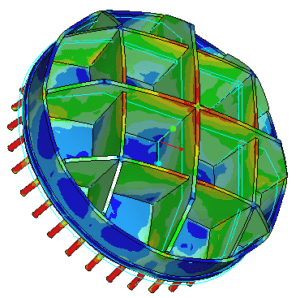
Introduction In this case study, a burst test was conducted to demonstrate the strength of a DN1200 Glass Fiber Reinforced Plastic (GRP) pipe. The objective
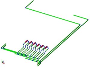
Introduction In the context of a compression station project, DRG conducted a comprehensive static stress analysis encompassing the plant inlet, slug catcher, and filter areas.

Introduction In this case study, we delve into a static stress analysis concerning a distillate water header within a remineralization unit of a desalination plant.

Benefit of computational simulation of a pulsation dampener compared to an analytical method Accumulators are used to reduce pressure pulsations from reciprocating pumps by adding

ON-DEMAND 🕖 60 MIN 🌏︎ ENGLISH Solving Vibrations In A Two-Phase Process Line Frank Bos Partner Get instant access Free. Recording + slide

ON-DEMAND 🕖 50 MIN 🌏︎ ENGLISH Surge and dynamic stress analysis for an offshore wind farm using BOSfluids Mark Groen Software Lead Engineer

ON-DEMAND 🕖 25 MIN 🌏︎ ESPAÑOL Integración de BOSfluids con Caesar II y otros programas de tensión de tuberías Uri Peker Engineer Get instant
ON-DEMAND 🕖 35 MIN 🌏︎ ENGLISH BOSfluids integration with CAESAR II and other pipe stress programs Ryan Metcalf Manager USA Get instant access

A manhole interrupts the load-bearing shell of an elbow or tee, so the component is regarded as a non-standard piping fitting. The three fittings here are two 20 inch long-radius elbows, EX-23 and EZ-22, in SA-234 Gr. WP11 Cl. 1, and one 32 inch ASME B16.9 welding tee, FB-11, in

Furnace F-501 at a refinery heats crude through radiant coils made of A312 TP316Ti stainless steel. Each coil enters the radiant section at grade level, runs 21 loops parallel to the refractory lined furnace wall, crosses over to the roof section, makes 8 further loops against the roof, and leaves

Two identical Visbreaker bottom pumps at an onshore refinery were due for replacement. The existing pumps were of single side suction execution, the new pumps of double side suction execution. For the new pumps a minimum straight length of five times the diameter (5D) was specified directly upstream of the

A gas line between the high and low pressure separators of a hydrocracking unit failed in service, probably through material fatigue caused by vibration. An additional 3-way stop was fitted just downstream of the TSO valve to reduce vibration levels, and vibration was then measured at nine locations on the

The crude heating system serves one of two distillation trains: crude is preheated in a convection box, heated in the radiant section of the furnace and carried by a feed line to the tower. Crude heating generates two-phase flow, whose fluctuations impose the unsteady unbalanced loads at elbows and tees

At a refinery, a branch connection designated W31056, the 2″ line that ties in to the high-pressure steam attemperator J-3103 (a desuperheater), failed in service. A similar failure had occurred about twenty years earlier, in 1992. On-site observations report periodic movement of the connecting header, line 6″-S31022, which contains the

A refinery operator is replacing two existing steel main cooling water headers with Glass Reinforced Epoxy (GRE) piping. The two changes were raised as Technical Change Requests, and this case study covers the second of them, the “lube” cooling water header. The GRE consists of a header and a branch

A wash oil line was vibrating in the vertical section downstream of its angle control valve. It has been reported that the vibration amplitude increases with increasing flow, and in the future the mass flow rate may still be increased further. No vibration measurements had been carried out, so the

Undesirable vibrations were observed in the wash oil line between two vessels during activation of the wash oil flow, most severe in the vertical section immediately downstream of the angle control valve. An earlier study had already identified slug flow as the most probable cause and proposed mitigation measures, and

The 10″ inlet and outlet lines of furnace H301 carry two-phase content during all process conditions. Under certain process conditions, staff reported feeling like getting seasick when standing on the platform of the furnace, and the piping was seen vibrating mainly near the furnace. The impact of these dynamic effects

A flue-gas overhead line runs from a third stage separator to a waste heat boiler. It carries gas at a maximum operating temperature of 740 °C upstream of the orifice chamber and is designed for 755 °C in the hot-walled sections. At those temperatures the hot-wall material, stainless steel A240

Two existing steel cooling water headers were to be replaced with Glass Reinforced Epoxy (GRE) piping under two Technical Change Requests. This case study covers the first request, for the main cooling water header “boiler”. The second, covers the “lube” header. A flexibility analysis was required, together with recommendations, to

An 8-inch line carrying two-phase content from a heat exchanger to a gasoil stripper at a refinery had been vibrating for years, mainly in the two shorter horizontal sections, one downstream of the heat exchanger and one just upstream of the stripper. The operator had reported vibration for 5 to

A line in the creep range, where the weight loads set the support design The line studied here is the revised fluegas overhead line between the third stage separator and the superheater. It operates at 725 °C in the hot walled sections and 200 °C in the cold walled section,

A coil anchored at both ends, with the cross-over overloaded In a refinery furnace, the radiant coil carries crude. Under a project designated high TAN, the existing carbon steel radiant coil piping is to be replaced by stainless steel, grade A312 TP316Ti. This account presents the stress analysis of the

Lines assessed 4 Pipe content Two-phase gas-liquid flow, all process conditions Flow regime, start-up Slug flow Flow regime, normal operation Annular flow Pipe material A 358 type 321, main material Design temperature 400 °C Design pressure 77.5 bar, Lines 1 and 3; 81.0 bar, Lines 2 and 4 Liquid slug

Line temperature 700 °C Design temperature 755 °C Design pressure 4.2 barg Pipe material A 312 type 304H Allowable stresses ASME B31.3 Appendix A Expansion loop 4 inch, 6,000 mm deep Creep-range service on the catalyst withdrawal line A waste catalyst line runs from the regenerator to the waste catalyst

Recently, fatigue cracks were discovered in the first-stage discharge line’s small-bore instrumentation branches of a hydrogen compressor. Initial investigations pointed to excessive out-of-plane vibrations as the primary driver of these failures. While the system was originally installed in 1995 with a pulsation study, and further axial supporting was added in

In industrial effluent systems, piping integrity is often threatened by the geotechnical behavior of the surrounding soil. This case study examines the peer review of a stress analysis for effluent pipelines situated between valve chambers. The primary challenge identified is differential settlement, where unpiled concrete pit walls shift relative to
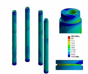
Introduction This case study presents the finite element analysis (FEA) and verification process conducted for the pressure-containing parts of the F35-340 actuator, developed by Actuator Technology Company. The primary goal was to demonstrate the structural integrity of the actuator under specified operating conditions and to ensure compliance with the requirements

This case study presents the fatigue assessment of the 28L oil separator (Atlas part number 1625481501), performed to verify the vessel’s durability under cyclical internal pressure in accordance with the AD2000 S2 standard. The separator is subject to a cyclic pressure loading from atmospheric pressure up to 15 barg, which

DYNAFLOW RESEARCH GROUP (“DRG”) Enters into Reseller Agreement with Quality Professional Software (“QPS”) RIJSWIJK, The Netherlands – January 24, 2024 (Dynaflow Research Group BV) –

Dynaflow Research Group and Seawind Ocean Technology announce collaboration focusing on technical readiness of floating offshore wind applications in the Mediterranean Sea. This landmark partnership