
New water hydrants were installed as part of an upgrade of the firewater system at a main degassing station. Each hydrant valve joins the steel hydrant part to the underground glass-reinforced epoxy (GRE) piping, and the GRE piping connects to steel piping coming from the above-ground equipment. The GRE is EST 20 with a 55 degree winding angle, ND 150 and a 2.4 mm structural wall. The design pressure is 20 barg, the maximum design temperature is 52 °C and the installation temperature is 21 °C. This case study covers the static stress analysis of the underground GRE piping.
Flange Loading on the GRE Piping
The design pressure is 20 barg. Because EST 20 GRE flanges are used, in principle there is no allowance for the accommodation of external loads under design conditions. Manipulation of the hydrants transfers moment loads to the GRE, and the steel piping coming from the above-ground equipment imposes moments on it.
CAESAR II Model and Load Cases
The piping was modelled and analysed in CAESAR II using two model files, one of which is the underground model. The pipe material properties and allowable stresses are based on data provided by the pipe manufacturer.
The model used the following properties:
- axial elasticity modulus of 12000 MPa
- hoop elasticity modulus of 20500 MPa
- shear modulus of 11500 MPa
- Poisson ratios of 0.38 under hoop load and 0.65 under axial load
- thermal expansion coefficient of 20 × 10⁻⁶ mm/mm/°C
- pipe specific gravity of 1.85
The pipe content is water at a density of 1000 kg/m³. The steel piping is a boundary to the GRE piping. It was modelled from a general overview drawing, with supports applied at logical positions.
Three load cases were analysed, each including the weight of the filled pipe:
- a hydrotest at 30 barg and 52 °C, with the test pressure
- an operational case at 20 barg and 52 °C, with the maximum design temperature and design pressure
- a sustained case at 20 barg and 52 °C, with the design pressure
Hydrant Restraints, Axial Stop and GRE Strengthening
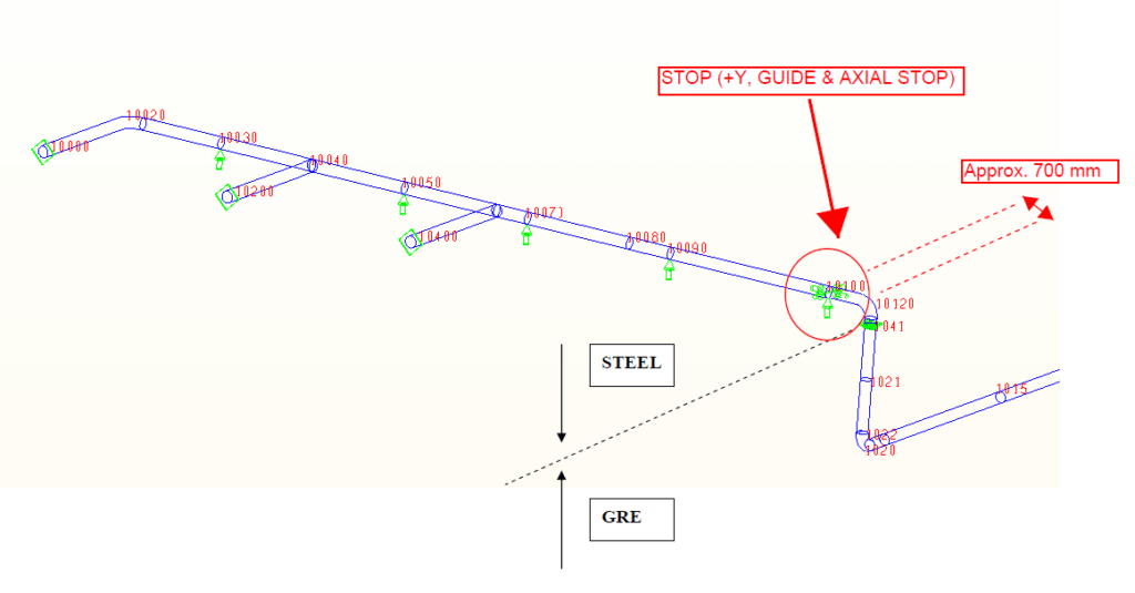
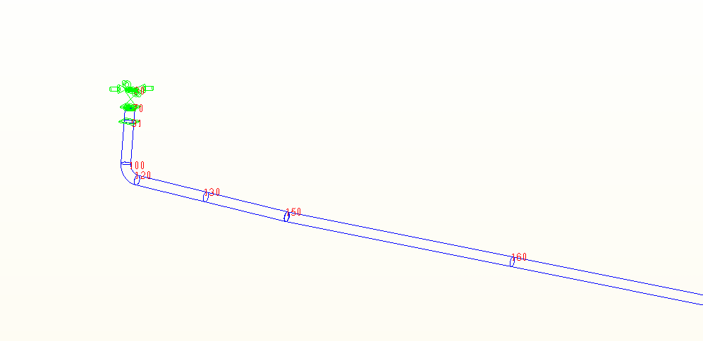
The top flange of each hydrant valve connected to the GRE piping is restrained in all directions except the vertical. The restraint is a clamp with brackets that connect the flange to the anchor foundation. This limits the moment loads transferred to the GRE by manipulation of the hydrants.
A rigid connection from the steel hydrant piping to the concrete floor is required to prevent operating loads on the hydrants from overloading the GRE flanges. In the model, the hydrant connection piping was anchored at grade level. A concrete floor was applied there, and the piping was assumed to be encased and fixed to the concrete. The pipe sections connected to the above-ground equipment were modelled as anchors.
Two adjustments to the standard arrangement are needed to bring stresses within allowable limits. The first is an axial stop in the steel piping coming from the above-ground equipment, near its intersection with the GRE piping, to limit the moments imposed by the steel piping. The second is strengthening of the GRE piping connected to that steel piping and of the underground bend.
Flange Check Basis and Cover Depth
According to a memo from the flange manufacturer, the qualified pressure is two times the rated pressure. The combined flange loads (internal pressure and external loading) were checked against the rated pressure, corrected by the applicable load-dependent part factor.
The cover depth is 908 mm on two isometrics and 978 mm on a third, in each case measured from the pipe centreline. No further data exist, so a global cover depth of 870 mm was assumed.
Pipe Stresses and Flange Loads
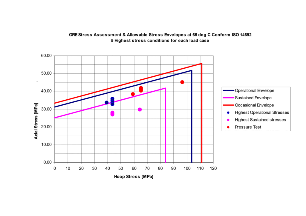
The GRE pipe stresses were assessed in accordance with ISO 14692 using the supplier material data. The assessment plots the highest stress conditions for each load case against the ISO 14692 operational, sustained and occasional allowable stress envelopes at 65 °C. Upon implementation of the recommendations listed in the next section, the computer results show that the static pipe stresses are acceptable. The GRE flange loads are moderate as a result of the measures taken, and are presented in the computer output. The stress assessment of the steel pipe sections is outside the scope of this calculation.
Recommendations for GRE Stresses and Flange Loads
Both conclusions depend on implementing three recommendations:
- the axial stop in the steel piping near the GRE intersection
- the strengthening of the GRE piping connected to the steel piping and of the underground bend
- the rigid connection of the steel hydrant piping to the concrete floor
The top flange restraint of each hydrant valve is also required, to keep the loads on the GRE flanges to a minimum.
Frequently Asked Questions
Why is an axial stop fitted where steel piping meets underground GRE piping?
The steel piping coming from the above-ground equipment imposes moments on the GRE. An axial stop in the steel piping, near its intersection with the GRE, limits those moments. Together with strengthening of the GRE piping at that connection and at the underground bend, it is one of the two adjustments needed to bring stresses within allowable limits.
How were the GRE flanges checked when there was no allowance for external loads at the 20 barg design pressure?
A memo from the flange manufacturer states that the qualified pressure is two times the rated pressure. On that basis, the combined flange loads (internal pressure and external loading) were checked against the rated pressure, corrected by the applicable load-dependent part factor.
How were hydrant operating loads kept off the GRE flanges?
Two measures address this. The top flange of each hydrant valve is restrained in all directions except the vertical, by a clamp with brackets connecting it to the anchor foundation. In addition, the steel hydrant piping is rigidly connected to the concrete floor, to prevent operating loads on the hydrants from overloading the GRE flanges.
Which load cases were analysed for the underground GRE firewater piping?
There were three cases, each including the weight of the filled pipe:
- a hydrotest at 30 barg and 52 °C
- an operational case at 20 barg and 52 °C, with the maximum design temperature and design pressure
- a sustained case at 20 barg and 52 °C, with the design pressure
What cover depth was used when the isometrics gave different values?
The isometrics show 908 mm on two drawings and 978 mm on a third, measured from the pipe centreline. No further data existed, so a global cover depth of 870 mm was assumed for the analysis.