
Vibrations had been seen in the piping of a reciprocating compressor plant and the operator of the plant was worried that fatigue cracks could occur. Therefore a study was conducted by DRG to determine how the vibration levels could be reduced and whether they were leading to stress levels exceeding the endurance limit. This article explains how the FEA model was tuned to the vibration measurements at the spring support, please see the full paper for more details and some of the other methods that were used.
Step 1: Vibration measurements on the lines that showed excessive vibration levels
A three-axis accelerometer was used at a limited number of locations to measure the vibrations levels on supports and piping (Figure 1).

The two-stage compressor operates at 295 RPM. Vibration measurement results of the second stage discharge line are shown in Figure 2 at 10 Hz. For reference the recommended limit for vibration levels is given as stated by the Energy Institute AVIFF. It shows that the vibration levels at the outlet of the pulsation damper are higher than expected. This results in a high axial vibration level at location 22 and a high lateral vibration level at location 23.

Step 2: FEA analysis to determine the resulting stresses
In Figure 3 the modal deflection shape at 8 Hz is shown as obtained from a beam type FEA model where the spring supports provide no axial restraint. If the spring supports are modeled as rigid in three directions no significant vibrations were found. Thus there was a significant difference between the measurements and the response of the piping based on the estimated vibrations due to the way the spring supports implemented in the model. To calculate the stress levels a forced mechanical response study was performed. The design stage pulsation results were used to determine the shaking forces.

Step 3: Fine tuning the modelling of the spring support

The spring support is shown in Figure 4. The lateral stiffness of the spring support was estimated using a shell FEA model of the strap. The level of axial restraint in the spring loaded supports depends on the friction between the support and the piping. The pre-load from the spring was estimated based on the dimensions of the spring. Dynamic friction is determined from the static friction as shown in Equation 1 where FF is the dynamic friction factor.

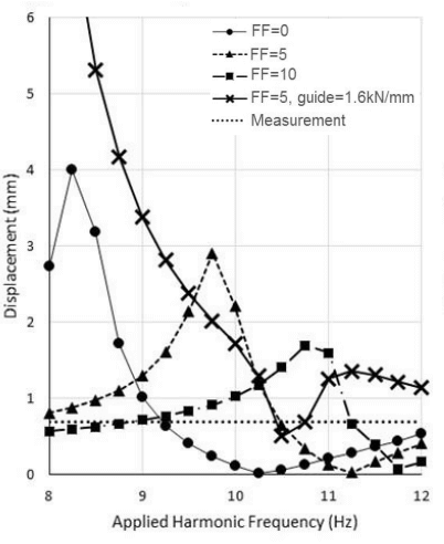
Dynamic friction, in contrast to static friction due to velocity of the vibrations, is not well defined by empirical values. The dynamic friction factor FF has therefore been used to vary the dynamic friction to obtain a best fit between the measurements and the beam type FEA analysis. Reviewing Figure 5 it can be seen that the frequency of maximum response is heavily dependent on the level of dynamic friction. Figure 5 shows that a dynamic friction of 5 with the guide stiffness gives a good match for this location. Is should be noted though that the choice of dynamic friction will be a compromise between the best fits at different points in the model.
This fitting is further complicated by the amplitude that is chosen for the shaking forces based on the design pulsation study, as there is no certainty that the pulsations are identical in the field. This discrepancy can only be solved by running the compressor at various speeds to check the response. However, in practice this is often not possible as either it is a fixed speed compressor or due to operational constraints. Therefore it is important to realise that the stress results from a tuned model determined from a study such as this are only applicable at the speed and power setting for which the measurements were taken.
Conclusions
This study shows that it is important to include realistic support stiffness estimates in the design stage and when diagnosing vibrations in the field. The combination of simple vibration measurements and a beam-element FEA model can be a powerful tool for determining stress levels and the likelihood of fatigue failure, but dynamic friction is not as predictable as static friction and thus a FEA model will most likely require tuning to match field measurements. It is important to realise though that the results are only applicable to the operating condition for which the measurements were taken.
For more details please check the full paper which includes more cases:
Fawcett (2016) – In-field vibration assessment of the piping of a reciprocating compressor plant.pdf