
Steam-Out Cycles of the Carbon Bed Vessels
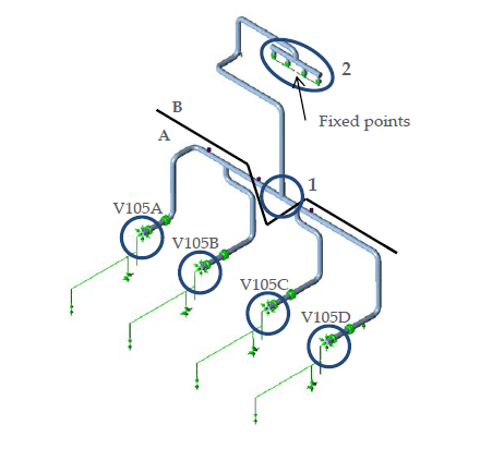
In the offgas cleaning system of an EBHP reaction section, vessels V105A to V105D absorb EB from the offgas on active carbon beds, because the EB has to be removed before flaring for environmental reasons. Once a bed is saturated, it is steamed out with LP steam at 180 °C.
Interconnecting line LP1045 runs between the vessels and heat exchangers E109A and E109B. With three of the four vessels active, each vessel is heated and cooled approximately 11 times per day, and section B has 34 cycles per day.
Crack History and Objective for Line LP1045
Fatigue cracks were first observed in 1980, and several sections of the system have been replaced multiple times since. The objective of the analysis was to determine the remaining lifetime of line LP1045, of the applicable tee connections and of the local wall connections of the line to vessels V105A to V105D.
Thermal Analysis of the Insulated Pipe
Temperature measurements cover 12 hours at the heat exchanger inlet and at the bottom of vessel V105A. No measurements were available for the pipe sections between each vessel and the manifold T-junction, so their wall temperatures were calculated with a transient thermal analysis in FE-Pipe.
The model represents a straight 10 inch schedule 10S pipe of SA-312 TP321 with 25 mm of insulation. The heat transfer coefficients were modified so that the cool-down times corresponded to the measurements. In this model, the pipe cools to ambient in approximately 80 minutes. Heating from ambient to 140 °C in the pipe sections between the vessels and the manifold T-junction takes approximately 5 minutes.
The temperature difference between the inside and outside of the pipe wall peaks at 3.7 °C two seconds after the start of shock heating. The resulting stress in the wall is estimated at 4.5 MPa, an order of magnitude lower than the stresses that contribute significantly to the fatigue life of the piping. Stresses due to rapid heating are therefore unlikely to be the cause of the fatigue cracks reported in line LP1045.
Piping Model and Fatigue Assessment Method
The CAESAR II model covers vessels V105A to V105D, heat exchangers E109A and E109B, and lines LP1045, LP1092 and LP1159. The vessels and heat exchangers are modelled with rigid elements that account for their thermal expansion. Nozzle flexibilities calculated in FE-Pipe are applied at the nozzle-vessel interface.
Eight temperature states, T1 to T8, span one cycle of the four vessels. At the start of each steaming phase (T1, T3, T5 and T7), the line of the active vessel is at 140 °C, the line of the previously active vessel is at 87 °C and the two other lines are at the ambient temperature of 21 °C.
Fatigue was assessed to ASME B31.3 paragraph 302.3.5, where the allowable stress range depends on the factor f = 6.0N^-0.2 and N is the number of full displacement cycles. ASME VIII Division 2 Annex 3.F was used to verify the results. Stress intensification factors (SIFs) from ASME B31.3 and from FEA were each assessed to both standards, which gives four result sets for each configuration.
Fatigue Lives of the Tees
The original configuration, with fabricated pipe-to-pipe tees, was assessed to validate the assessment method and to verify that the fatigue issues can be reproduced. Nodes 150, 190 and 200 are the three tees at the bottom of the system in line LP1045-2, at 11 cycles per day. The effect of a pad installed at some time was not investigated.
With ASME B31.3 SIFs assessed to ASME B31.3, the stress ranges at nodes 150, 190 and 200 are 153.4, 166.5 and 187.7 MPa, and the expected lifetimes are 7, 5 and 3 years. With ASME B31.3 SIFs assessed to ASME VIII Division 2, the lifetimes are 13, 10 and 7 years. With FEA SIFs, the stress ranges are 78.6, 112.9 and 93.5 MPa. The lifetimes assessed to ASME B31.3 are more than 100, 35 and 90 years, and those assessed to ASME VIII Division 2 are more than 100, 16 and 36 years.
In the original configuration, the largest stress range at nodes 190 and 200 is between T1 and T5 (vessels V105A and V105C active), and at node 150 between T1 and T3 (vessels V105A and V105B active). At nodes 1150, 1160, 1180, 1220 and 1240, the expected lifetime is more than 100 years in all four result sets. The report concludes that with pipe-to-pipe junctions a fatigue problem is very likely within the design life at nodes 150, 190 and 200.
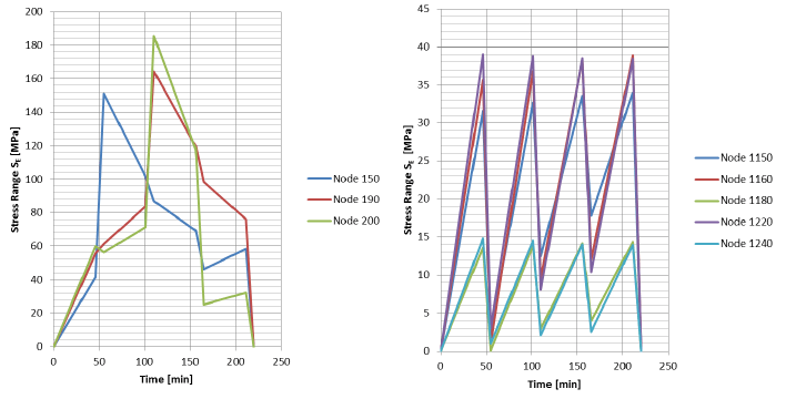
In the as-built configuration, the welding tees at nodes 150, 190 and 200 were installed in 2012 and the welding tee at node 1150 in 2002. Nodes 1160, 1180, 1220 and 1240 remain pipe-to-pipe. The stress ranges at nodes 150, 190 and 200 are 73.9, 80.1 and 90.1 MPa with ASME B31.3 SIFs. The expected lifetime is more than 100 years at all eight nodes in all four result sets, and fatigue is found not to be an issue for the interconnecting line between the vessels and the heat exchangers with these welding tees included. The cycles per day are conservatively taken for three vessels active, the case with the most cycles per day.
The heat exchanger temperature variation is unknown and is assumed equal to the temperature measured at the heat exchanger inlet. For a rest life of 20 years at the pipe-to-pipe tees at nodes 1160, 1180, 1220 and 1240, the maximum temperature difference between the heat exchangers and the surrounding pipe should not exceed 10 °C, where the heat exchanger temperature is that of the heat exchanger closest to the piping. The heat exchangers are modelled with rigid elements, so all thermal displacement causes stress in the pipe-to-pipe tees instead of deforming the heat exchanger. The real heat exchanger has some flexibility, which gives a longer expected life or a larger allowable temperature difference.
Effect of Tee Type and Nozzle Loads on Fatigue Life
The SIFs of the fabricated pipe-to-pipe tees are approximately twice those of the welding tees, which are less sensitive to fatigue. According to the equation for f in ASME B31.3, this decreases the allowable number of cycles of the fabricated tees by a factor of 32. In the as-built configuration, the stress ranges at nodes 150, 190 and 200 are decreased by a factor of 2 relative to the original configuration, due to the decreased SIFs of the welding tees. The reduced peak stresses of welding tees relative to pipe-to-pipe connections resolve the apparent fatigue issues seen in the original configuration in the interconnecting lines between the vessels and the heat exchangers.
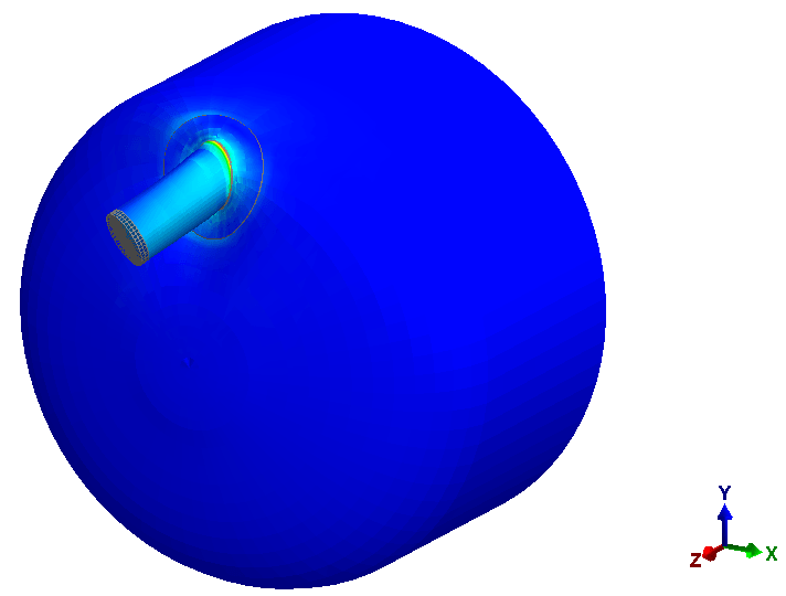
The nozzle loads from the CAESAR II model were applied to an FE-Pipe model of nozzle N2 and the head of vessel V105A. The highest moment range, between load case 11 and load case 15, cycles 11 times per day with three vessels active. The resulting stress amplitude is 25.7 MPa, below the endurance limit of the ASME VIII Division 2 fatigue curve for carbon, low alloy and high alloy steels. Fatigue is not an issue for the nozzle considering these loads.
Frequently Asked Questions
How quickly does an insulated steam line heat up and cool down?
In the FE-Pipe model of a 10 inch schedule 10S pipe with 25 mm of insulation, the pipe cools to ambient in approximately 80 minutes. Heating from ambient to 140 °C in the sections between the vessels and the manifold T-junction takes approximately 5 minutes.
Why did the pipe-to-pipe tees show a fatigue problem and the welding tees did not?
The SIFs of the fabricated pipe-to-pipe tees are approximately twice those of the welding tees, which decreases the allowable number of cycles by a factor of 32 according to the ASME B31.3 equation for f. With ASME B31.3 SIFs assessed to ASME B31.3, the original tees at nodes 150, 190 and 200 gave expected lifetimes of 7, 5 and 3 years. The as-built configuration gives more than 100 years at all eight nodes.
Is fatigue an issue at a vessel nozzle loaded by thermally expanding piping?
For nozzle N2 on vessel V105A, the stress amplitude is 25.7 MPa. This is below the endurance limit of the ASME VIII Division 2 fatigue curve, so fatigue is not an issue for the nozzle considering these loads.