This case study examines the structural integrity of header boxes in an industrial air cooler heat exchanger subjected to cyclic thermal loading and static pressure. In processes where heat exchangers experience significant temperature fluctuations, ensuring the longevity and safety of critical components is paramount. The primary objective of this study is to assess the header box’s ability to withstand repeated thermal cycles over its intended 20-year lifespan while maintaining compliance with ASME VIII Division 2 (Design by Analysis) 2019 standards.
The heat exchanger operates in a demanding environment, cycling between ambient and high temperatures every few hours, accumulating thousands of cycles over its operational life. This thermal cycling, combined with constant static pressure, poses potential risks to the structural integrity of the header boxes. This case study aims to provide a comprehensive analysis of the thermal stresses and fatigue effects on the system, ultimately determining if the current design meets the required safety standards or if modifications are necessary.
Thermal Fatigue Risk in Air Cooler Heat Exchanger Header Boxes
The specific technical challenge addressed in this case study is the assessment of the header box’s structural integrity under the following conditions:
- Cyclic thermal loading from 21°C to 290°C every 480 minutes.
- A total of 21,900 thermal cycles over a 20-year operational lifespan.
- Constant static pressure of 52.4 barg during operation.
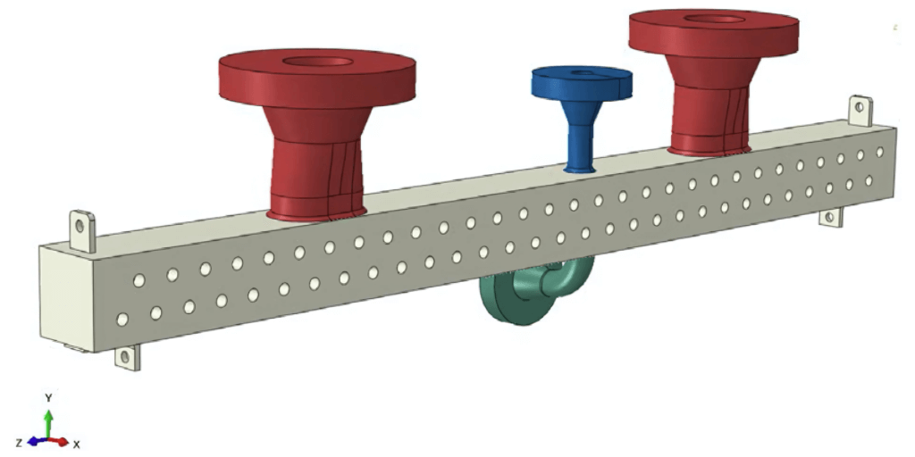
- Cyclic external nozzle loads applied to the header box nozzles (conservatively taken as fully secondary and at 3x API 661).
The primary constraint is the need to comply with ASME VIII Division 2 (Design by Analysis) 2019 standards, which set strict requirements for pressure vessel components under cyclic loading conditions. The analysis must demonstrate that the header box can withstand the specified operational conditions without failure due to fatigue or ratcheting.
Step-by-Step Approach to Evaluating Structural Integrity
To analyze the problem and assess the header box’s structural integrity, the following methodology was employed:
Finite Element Analysis (FEA):
- A linear elastic FEA approach was employed using Abaqus 2023 software to simulate the header box’s behavior under thermal and pressure loads.
- A full transient thermal analysis was performed across a complete 480-minute cycle, ensuring accurate temperature and stress predictions over time.
Thermal Analysis:
- The temperature distribution across the header box was calculated throughout the operational cycle, identifying points of maximum thermal gradients and temperature differences.
- The analysis captured the internal and external temperature extremes, with a particular focus on the maximum temperature difference, which occurs approximately 88 minutes into the cycle.
Critical Locations Assessment:
- Five key areas were identified for detailed analysis:
- Inlet nozzle to header box welds
- Header box corner welds
- Vent to header box welds
- Drain to header box welds
- Tube-to-tubesheet “key & lock” connections
Stress Analysis:
- Equivalent von Mises stresses were calculated for the entire thermal cycle. Special attention was given to areas with high-stress concentrations, particularly during peak thermal gradients.
- Stress variations were studied to identify locations with potential fatigue and ratcheting risks.
Fatigue and Ratcheting Checks:
- The ASME VIII Division 2 (2019) guidelines were applied to evaluate fatigue and ratcheting behavior across the identified critical locations.
- The full cycle count (21,900 cycles over 20 years) was incorporated into the analysis to account for long-term operational conditions.
Critical Stress Areas and Cyclic Behavior of the Header Box
The FEA analysis of the header box revealed several key findings:
- Thermal Results:
- The maximum internal temperature reached 282°C on the header box.
- The maximum external temperature was 203°C, observed on the inlet nozzles.
- The maximum temperature difference occurred approximately 88 minutes into the cycle, shortly after the fluid contents reached the peak temperature of 290°C.
- Stress Results:
- The highest stresses occurred when the thermal gradient through the equipment walls was at its largest, approximately 88 minutes into the cycle.
- The lowest stresses were observed during the cool-down phase of the cycle.
- Cyclic Behavior:
- The analysis confirmed that the cooldown period between cycles was sufficient to ensure no interaction between successive thermal cycles.
- Critical Locations Performance:
- All five critical locations (inlet nozzle to header box welds, header box corner welds, vent to header box welds, drain to header box welds, and tube-to-tube sheet connections) conformed to ASME B&PV VIII-2 fatigue and ratcheting checks for the full cycle count over the operational lifespan.
Evaluation of Current Design: Structural Integrity and Compliance
The effectiveness of the current header box design was evaluated against the initial objectives and ASME standards:
- Structural Integrity:
- The analysis confirms that the header box maintains its structural integrity throughout the specified thermal cycles.
- All critical welds and connections pass the ASME B&PV VIII-2 fatigue and ratcheting checks.
- Temperature Management:
- The design effectively manages the thermal gradients, with maximum temperatures within expected ranges.
- The cooldown period between cycles is sufficient to prevent thermal interaction between successive cycles.
- Stress Distribution:
- While high stresses were observed in certain areas, these were attributed to modeling artifacts rather than actual design issues.
- The overall stress distribution throughout the thermal cycle remains within acceptable limits.
- Compliance with Industry Standards:
- The current design fully complies with ASME VIII Division 2 (Design by Analysis) 2019 standards for all specified cycles over its intended lifespan.
This case study of the air cooler heat exchanger header box demonstrates the critical importance of thorough thermal stress analysis in high-temperature cyclic applications. By confirming the structural integrity of the header box under these demanding conditions, this case study demonstrates the robustness of the current design and provides confidence in its long-term performance.