
Cyclic Thermal Duty in a Gas Treatment Air Cooler
An air-cooled heat exchanger for a gas treatment plant is subjected to a varying inlet temperature. In the analysed winter case, which has the largest temperature variation, the fluid cycles between 7.5°C and 288°C during each 100-minute cycle. The first part of the cycle, in which the temperature rises, is the hydrocarbon production phase and the second part is the water production phase. The scope covers 157,788 cycles over a 30-year design life, and the repeated cycling could result in thermal fatigue issues.
The critical areas were expected to be the intersection between the inlet nozzle and the inlet header box, and the combined first pass return and outlet header box, where a partition plate separates two gas chambers. The aim was to determine whether these areas conform to the ASME B&PV VIII-2 fatigue assessment for that number of cycles. A primary load assessment and a fatigue assessment of the tube to tubesheet connection are outside the scope.
Differential Thermal Expansion at the Nozzle and the Partition Plate
At the nozzle and header box intersection, the nozzle and the header box heat at different rates. At 59 minutes, when the inlet fluid reached 288°C, the nozzle had heated to 260°C and the header box corner to 200°C on the inside face of the intersection. The cooler header box further from the intersection restrains the expansion of the intersection, and high stress intensity arises at the weld toes and the header box corner.
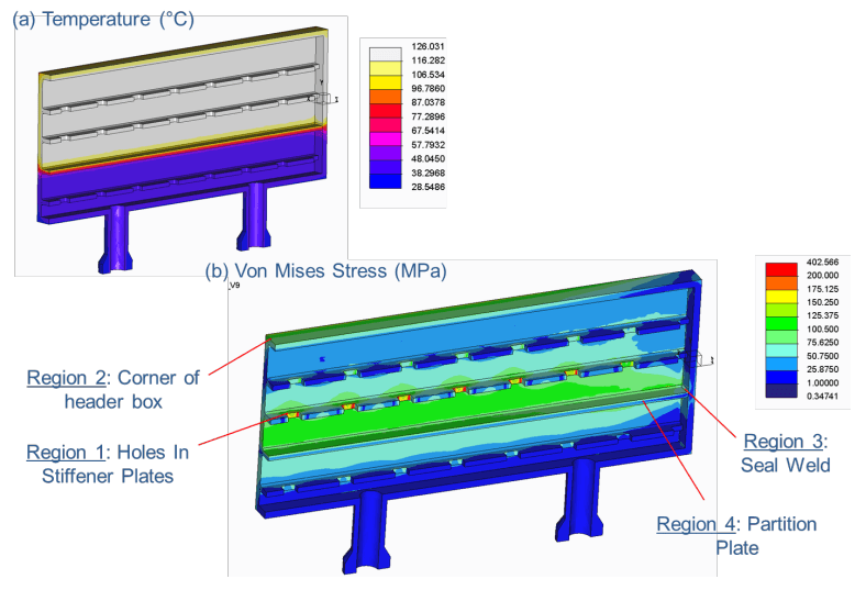
In the combined first pass return and outlet header box, with the inlet fluid at 288°C, the wall temperature is approximately 126°C in the upper half and around 40°C below the partition plate, and the largest temperature gradient is near the partition plate. The upper chamber expands along the axis of the header box more than the lower chamber. The difference in thermal expansion between the two chambers generates a bending stress in the partition plate. The stiffener immediately above the partition plate is in compression, because the cooler lower chamber constrains its expansion, and the stiffener below it is in tension. High stress intensity also arises in the seal weld between the partition plate and the end wall, because the weld restricts the deflection of the end wall under the thermal loads.
Three Finite Element Models and Their Inputs
In all analyses, properties of SA182 F304L and SA240 Gr. 304L were taken from ASME B&PV Section II Part D, except specific heat, which is not available there, and mean values were used according to the minimum and maximum temperatures in the cycle.
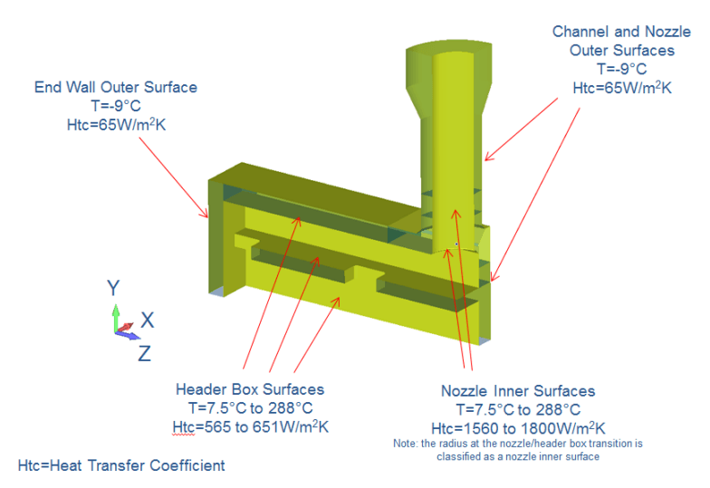
Model 1 represented the nozzle and header box intersection under thermal loads. It was built in FEMAP with a Nastran engine as a quarter model, and a transient thermal analysis applied the temperature variation through the 100-minute cycle. The inner surface thermal boundary conditions varied between 7.5°C and 288°C, with heat transfer coefficients of 1560 to 1800 W/m²K at the nozzle and 565 to 651 W/m²K at the header box, and the outer surfaces were exposed to air at -9°C with 65 W/m²K. The inner coefficients were calculated with the standard pipe flow relationship Nu = 0.023Re^0.8Pr^0.3. The stiffener inside the header box was included so that the flexibility of the header box side wall was not over-estimated, and a grid sensitivity study was conducted to ensure sufficient grid resolution.
Model 2 used FEMAP with the full header box cross-section, because the nozzle loads are not symmetric, and applied either the nozzle loads or the 97 barg design pressure. The nozzle loads are 2 times the loads in Table 4 of API 661, are treated as 100% secondary and cycle between zero and 2 times the API 661 load; the worst-case combination of force signs was taken. The reduction in stiffness from the tube holes in the side wall was included.
Model 3 represented the combined first pass return and outlet header box in PTC CREO as a half model from the centre line of the header box, so that the bending due to thermal loads is modelled correctly, with thermal and pressure loads applied. Nozzle loads were excluded because their impact on the critical regions is negligible. The thermal load was a quasi-static case equal to the maximum temperature in the cycle, which was judged appropriate because the heat transfer coefficients in the upper and lower chambers were very similar. The first pass return chamber inner surfaces were at 126°C with 1595 W/m²K, the outlet chamber inner surfaces at 45°C with 1468 W/m²K, and the outer faces exposed to air at -9°C with 65 W/m²K. No low-temperature case was assessed, because both chambers cool at a similar rate and remain above the mean ambient temperature.
Plasticity, Fatigue and Ratcheting Checks to ASME B&PV VIII-2
Three checks were applied: a plasticity (shakedown) check to Part 5.5.3.2, a fatigue check against the S-N curve to Part 5.5.3, and a ratcheting check to Part 5.5.6.1. Thermal and nozzle loads were cyclic and the design pressure was steady, so thermal plus nozzle loads were combined for the plasticity and fatigue checks, and thermal, pressure and nozzle loads for the ratcheting check.
Stresses in the welded regions were linearised along Stress Characterisation Lines (SCLs), and the maximum stresses from the thermal and nozzle loads were added to give the total cyclic stress range. The nozzle and header box fatigue tables use 157,680 desired cycles. The design pressure is slightly conservative compared with the operating pressure, and the inlet nozzle analysis is conservative for the outlet nozzle, whose thermal loads are milder.
Results for the Nozzle Intersection and First Pass Return/Outlet Header Box
At the nozzle and header box intersection, the plasticity check conformed, with fractions of 0.50 at SCL1, 0.50 at SCL2 and 0.45 at SCL3 of the 320 MPa allowable structural stress. The fatigue check conformed at Point 1 (inside face of the intersection), Point 4 (header box corner) and SCL1 to SCL3, with life fractions from below 0.01 to 0.03; the highest, 0.03, was at SCL2 under combined thermal and nozzle loads. The ratcheting check conformed under combined thermal, pressure and nozzle loads, with fractions of 0.54, 0.65 and 0.66 of the 320 MPa allowable range at SCL1 to SCL3.
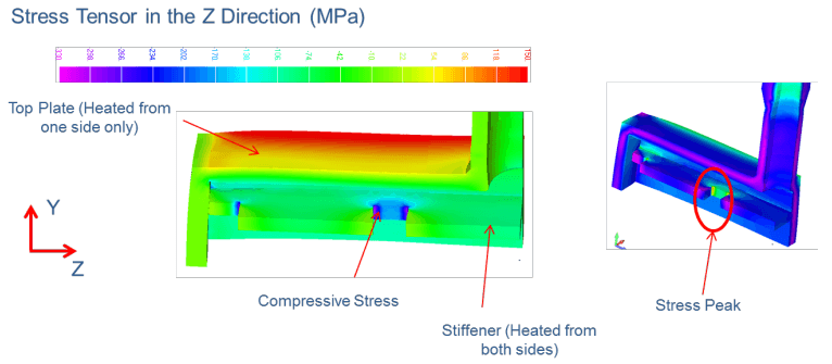
The stiffener plate in the nozzle and header box model conformed with the fatigue and ratcheting checks only with a concession. The top plate is heated from one side only and the stiffener from both faces, so the stiffener reaches a higher temperature, and the top plate and outside plate restrain its expansion. This produces a compressive stress peak, in the direction of the header box axis, at the curve of the stiffener hole. By the method of Part 5.5.3, the fatigue life of the stiffener plate is used up within about 25% of the design life.
In the first pass return and outlet header box, Region 1 (the holes in the stiffener plates) had fractions of the allowable value of 0.50 for plasticity, 0.08 for fatigue and 0.92 for ratcheting, at the worst case of SCL1A and SCL1B. The assessment concludes that the stiffener plate in this header box conforms with the fatigue and ratcheting checks with a concession.
Region 2 (corner of the header box), Region 4a (partition plate away from the seal weld) and Region 4b (partition plate next to the seal weld) conformed with the plasticity, fatigue and ratcheting checks. The fractions of the allowable value for plasticity, fatigue and ratcheting were 0.43, below 0.01 and 0.66 at Region 2; up to 0.34, below 0.01 and 0.59 at Region 4a; and up to 0.43, 0.11 and 0.65 at Region 4b.
The seal weld (Region 3) was not included in the fatigue analysis because it does not contribute to the mechanical integrity of the header box. Its failure would only allow leakage of process flow between the two chambers, in a quantity that the client quoted as similar to a drainage hole. Region 4b was also assessed with the seal weld assumed to have failed and conformed with all three checks.
Stiffener Plate Concession and Heat Transfer Coefficient Caveat
Most of the cyclic stress range in the stiffener is compressive, and crack growth is predominantly caused by tensile loads. The client’s concession, based on its experience and a comment in EN13445-3 Annex Q, takes compressive stresses at 60% of their calculated value for the fatigue and ratcheting checks. For ratcheting, the structural stress range was constructed from 60% of the compressive stress and 100% of the tensile stress.
With this treatment the stiffener plate has a peak equivalent stress of 330 MPa at the end of heating, a stress range of 418 MPa and a stress amplitude of 209 MPa, which gives 446,000 permissible cycles against 157,680 desired cycles and a life fraction of 0.35. The ratcheting fraction is 0.84 of the 320 MPa allowable range. The treatment is not explicitly permitted in ASME B&PV VIII-2 and does not strictly conform with it or with EN13445-3.
The first pass return and outlet header box results use the former, optimistic heat transfer coefficient inside the header box, on the understanding that a higher coefficient would be conservative. The nozzle and header box model uses the lower updated header box values. The analysis of the stiffener in the nozzle and header box model shows that with a lower, more realistic coefficient the stiffener stresses could become more critical. The client judged that no recalculation is necessary for the stiffener plate in the first pass return and outlet header box, based on its experience with the inlet header box stiffener calculation. With the 60% treatment applied, it could be judged that the fraction of life used would not detrimentally exceed, if at all, the Region 1 values, and a recalculation would be required for complete certainty. With these concessions on the stiffener plates, the heat exchanger conforms with the ASME B&PV VIII-2 allowable values for the 30-year design life.
Frequently Asked Questions
Why did the stiffener plate need a concession in the ASME VIII-2 fatigue assessment of an air cooler header box?
The stiffener is heated on both faces while the top plate is heated on one, and by the Part 5.5.3 method its fatigue life is used up within about 25% of the design life.
Can compressive stresses be taken at 60% in an ASME B&PV VIII-2 fatigue check?
The client applied this as a concession based on its experience and a comment in EN13445-3 Annex Q, and it is not explicitly permitted in ASME B&PV VIII-2.
Which loads are combined in the ASME VIII-2 plasticity, fatigue and ratcheting checks?
Thermal plus nozzle loads for plasticity and fatigue, and thermal, pressure and nozzle loads for ratcheting.