
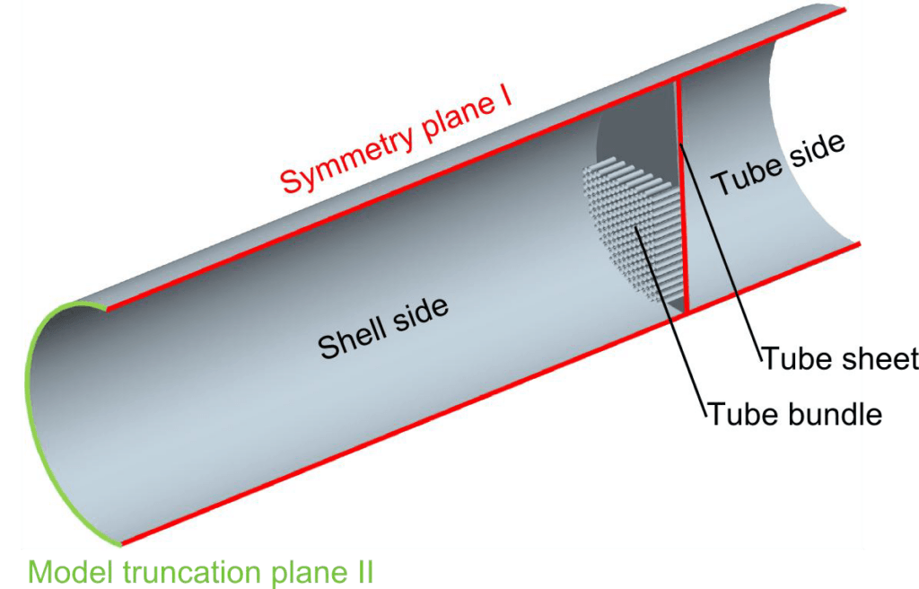
Two identical condensers cool sulphur gas to a temperature close to its dew point. The gas passes through 363 SA-179 tubes of 38.1 mm outside diameter and 8840 mm straight length, set on a 48 mm triangular pitch between two stationary tube sheets. On the shell side, water maintains a bed at 120 °C that embeds a semi-cylindrical tube sheet. The SA-765 Gr. II tube sheets are 45 mm thick, are not rotationally symmetric and have one plane of symmetry. The shell (shell side) and the channel (tube side) are SA-516 Gr.60, with an internal diameter of 1500 mm.
Large thermal gradients were expected across and along the tube sheet, which could lead to thermal fatigue. Dynaflow assessed the tube sheet, the tube sheet-to-shell junction, the tube sheet-to-channel junction and the tube-to-tube sheet welds, using a finite element model and the rules of ASME VIII Division 2.
Tube Sheet Thermal Gradients and Design Load Cycles
The condenser is divided into three sections: the inlet channel (section 1), the shell (section 2) and the outlet channel (section 3). Each section is split at the liquid level into a part above (A) and a part below (B).
In normal operation (case 1), the shell side film coefficient is 50 W/m²/°C in section 2A and 2600 W/m²/°C in section 2B. This difference in film coefficients produces a temperature difference of about 80 °C within the tube sheet. A temperature difference of about 155 °C exists between the shell side and the tube side.
The upper part of the tube sheet is hotter than the lower part and expands more in its plane. At the transition between the hot and cold areas, the upper part forces the lower part to follow its displacement. This causes a region of higher stress in the tube sheet at the elevation of the liquid surface. The lower part is at about the shell temperature and does not follow the radial expansion of the channel. As a result, high stresses develop along the lower attachment of the tube sheet to the channel.
Pressure adds a second load. Design case 11 places a pressure difference of 6.5 bar across the tube sheet, which bends it out of plane. The tubes resist this movement and carry an axial force into the tube-to-tube sheet welds.
The number of load cycles a vessel will see is often not known before design. For most vessels, 7000 cycles is typically applied as a default design value, which corresponds approximately to one cycle each day over a design life of twenty years.
For carbon steel with an ultimate tensile strength below 550 MPa, 7000 cycles on the fatigue curve gives an allowable stress range of roughly 560 MPa. For most higher-grade carbon steels, this is roughly twice the yield stress, written 2 × Sy,avg, where Sy,avg is the average of the yield stress in the cold and hot states. It is also roughly three times the allowable stress.
FE Brick Model with Symmetry and Truncation Planes
The model was built in Pro/Engineer from three element types:
- 3D bricks for the shell, channel and tube sheet, which give full detail of their stresses and temperatures
- 2D shells for part of each tube
- 1D beams for the rest of each tube
The tube holes are modelled.
Two planes of symmetry reduce the size of the model. Symmetry plane I is axial, cuts the tube sheet in two parts and carries a mirror symmetry condition. Model truncation plane II is perpendicular to plane I and cuts the length of the condenser in two parts. Plane II is anchored in all directions except the radial one, so the shell can expand radially.
Truncation at plane II is permitted because there is full symmetry in structure and pressure design. Thermally, the truncation affects only the tubes, which are connected to both tube sheets.
Anchoring the tubes axially at plane II is conservative. Differential thermal conditions between the shell and channel bend the tube sheet out of plane. Because the channel is at the higher temperature, the tube sheet bends towards the channel closure. This effect is smaller at the outlet side (section 3), where the temperature difference is smaller. Assuming symmetry therefore gives the largest tube forces, because both tube sheets are taken to expand by the largest amount. However, the contribution of pressure bending was seen to be far more dominant.
Insulation Film Coefficient, Tube Beams and Load Cases
The insulation is not modelled directly. Instead, an equivalent external film coefficient was calculated for the cylindrical parts in sections 1 and 2, for cases 1 and 6. The calculation used the single-layer relation in section D-Eb 3 of the VDI-Wärmeatlas, an average wind speed of 7 m/s and an ambient temperature of -7 °C. Section 3 is not considered because its internal temperature differences are small. The design cases have specified shell temperatures that do not depend on external factors.
To avoid modelling the tubes in full 3D, each tube is represented as a 1D beam, anchored axially at plane II with radial translation free. Each beam connects to the brick elements of the tube sheet through a rigid link and 2D shell elements, which avoids stress singularities at the connection.
The 2D shell elements are five tube sheet thicknesses long, so the force spreads evenly into the tube sheet. They also continue through the holes and spread the force over the inner surface of each hole. At symmetry plane I only half tubes are modelled, so their beams carry half the stiffness of a full beam to avoid doubling the stiffness there.
Four load cases are defined for assessment to ASME VIII Division 2:
- one operating condition (case 1)
- one emergency condition (case 6)
- two design conditions (cases 10 and 11)
Case 11 has the largest pressure difference across the tube sheet. Following correspondence with the client, it is used for the primary stress assessment only, because its specified temperature conditions have no physical meaning.
Case 10, with full vacuum in the shell, has a much smaller pressure difference but may be critical for stability. That check is covered by a separate design calculation to ASME VIII Division 1 section UHX.
Cases 1 and 6 are used for the secondary stress assessment.
ASME VIII Division 2 Primary and Secondary Stress Results
Stresses were assessed for the whole model and are reported at the most critical locations.
Primary stress assessment for plastic collapse and burst
The primary assessment uses case 11, with pressure only. It checks the linearised local primary membrane stress PL, and PL+PB, where PB is the general bending stress, against 1.5 × Sh, where Sh is the hot allowable.
Linearisation along each stress concentration line separates the stress into membrane, bending and non-linear parts. The non-linear part is omitted from the primary assessment.
Displacements and rotations are largest in the unperforated part of the tube sheet, which has no support from the tubes. The largest von Mises stress, 242 MPa, is at the junction between this part and the cylindrical shell.
The highest linearised stress is at location I, on the shell side at the top of the tube sheet-to-shell transition. There, a PL of 26 MPa and a PB of 141 MPa give a PL+PB of 167 MPa, against 1.5 × Sh of 187.1 MPa at 330 °C.
Two further locations are assessed against 1.5 × Sh of 178.1 MPa at 370 °C:
- On the tube side of the transition, the highest PL+PB is 124.4 MPa, at location 1.
- In the tube sheet itself, the highest PL+PB is 79.2 MPa, at location B.
Between the tube holes, the average bending stress is found by averaging the surface stress according to ASME VIII-2 table 5.6. At the three most critical ligaments it is 75.4, 74.7 and 75.4 MPa, against the same 178.1 MPa.
All values are within the allowable limits of the code.
Secondary stress assessment for low cycle fatigue
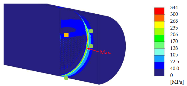
The secondary assessment combines the primary stresses PL+PB with the secondary stresses Q caused by thermal expansion. It checks the sum against an allowable stress range of 2 × Sy,avg. The local stress concentrations are conservatively included, so the highest peak stress is the value compared with this limit.
| Case | Location | Highest PL+PB+Q (MPa) | Allowable (MPa) | Temperature (°C) |
|---|---|---|---|---|
| 1 | Inside of the tube sheet-to-channel attachment | 344 | 450.9 | 250 |
| 6 | Tube side | 187 | 434.1 | 330 |
Tube-to-tube sheet weld assessment
The welds are assessed by manual calculation from the axial force in the highest loaded tube, with the whole force taken by the weld.
In the primary assessment (case 11), the largest force is 6342 N, on the most central tube (tube 1,1). It gives a weld stress of 22.0 MPa, 53% of the allowable of 41.65 MPa. That allowable is 0.49 × Sh according to ASME VIII Division 1 UW-15, with Sh the hot allowable of the weakest material in the junction.
The secondary assessment applies a maximum stress concentration factor of 4 for fillet welds, according to ASME VIII-2 table 5.11. The allowable is 2 × Sy,avg, which is 300 MPa. The highest forces are at the upper row of tubes:
- In case 1, 2184 N on tube 13,1, towards the edge of the tube sheet, gives 30.4 MPa.
- In case 6, 6464 N on tube 1,1 gives 89.9 MPa.
Normal Operation and Emergency Case Compared
The emergency case (case 6) has the largest temperature difference between the channel and the shell, 200 °C. Its highest PL+PB+Q, 187 MPa, is still lower than the 344 MPa of normal operation.
In case 6 the tube sheet is at a uniform temperature, about the average of the channel and shell temperatures. The deflection curve between the channel and shell is therefore relatively smooth, which limits the stresses compared with case 1. The tube sheet bends out of plane mainly because of the pressure difference between the tube side and the shell side, and the attached tubes prevent its lower part from bending out of plane. Temperature differences between the channel, shell and tube sheet cause additional stresses at the junctions.
In case 1 the tube sheet temperature is not uniform. Its lower part is at about the shell temperature while its upper part is hotter, which produces the stresses at the lower attachment to the channel and at the liquid surface.
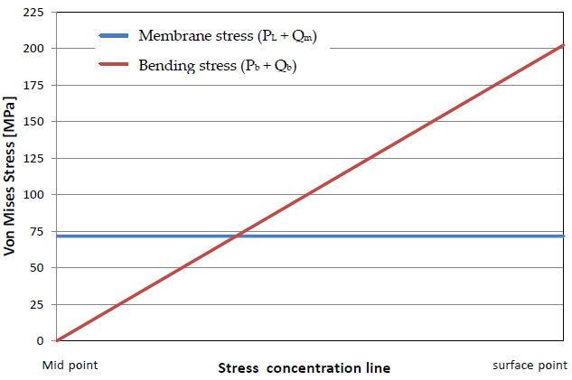
Case 1 also gives the highest stresses around the hub joint that connects the tube sheet to the shell and channel. These stresses are highest at the lower part of the condenser. The plot below shows the membrane and bending components of the von Mises stress along a stress concentration line at the lowest point.
Conservative Assumptions and 7000-Cycle Outcome
The assumptions recorded as conservative are:
- the axial anchoring of the tubes at plane II
- the inclusion of local stress concentrations in the secondary assessment
- the force at the tube-to-tube sheet junction being taken entirely by the welds, with friction of the expanded tube neglected
- tube temperatures in the calculations at or below the specified values
- allowable stresses based on the ASME VIII Division 1 tables of ASME section II part D
All stresses comply with the ASME VIII Division 2 stress limits, and no geometric modifications are required. A vessel that complies with the low cycle fatigue assessment for carbon steels in ASME B&PV Code Section VIII is generally fit for at least 7000 load cycles. The condensers are suited for a total of 7000 operation cycles.
Frequently Asked Questions
Why is the tube sheet stress higher in normal operation than in the emergency case?
In the emergency case (case 6) the tube sheet is at a uniform temperature, about the average of the channel and shell temperatures, so the deflection curve between the channel and shell is relatively smooth. In normal operation (case 1) the lower part of the tube sheet is at about the shell temperature and the upper part is hotter. This causes higher stresses at the lower attachment to the channel and at the liquid surface. The highest PL+PB+Q is 344 MPa in case 1 and 187 MPa in case 6, although case 6 has the larger temperature difference between channel and shell, 200 °C.
How can a 242 MPa von Mises stress pass a 187.1 MPa primary stress limit?
The primary assessment to ASME VIII Division 2 checks linearised stresses, not the peak von Mises value. Linearisation along each stress concentration line separates the stress into membrane, bending and non-linear parts, and the non-linear part is omitted. At the tube sheet-to-shell transition the highest linearised PL+PB is 167 MPa, against 1.5 × Sh of 187.1 MPa at 330 °C.
What allowable stress range is used for the low cycle fatigue check?
Twice the average yield stress, 2 × Sy,avg, where Sy,avg is the average of the cold and hot yield stresses. For carbon steel with an ultimate tensile strength below 550 MPa, 7000 cycles on the fatigue curve gives an allowable stress range of roughly 560 MPa, which for most higher-grade carbon steels is roughly 2 × Sy,avg. The 7000 cycles are a default design value, approximately one cycle a day over twenty years.
How were the tubes connected to the brick tube sheet in the FE model?
Each tube is a 1D beam joined by a rigid link to 2D shell elements, which connect to the brick elements of the tube sheet without stress singularities. The shell elements are five tube sheet thicknesses long and continue through the holes to spread the force over their inner surface. Half tubes on the symmetry plane have beams with half the stiffness of a full beam.
How are the tube-to-tube sheet welds assessed?
By manual calculation from the axial force in the highest loaded tube, with the force taken entirely by the weld. The primary check uses 0.49 × Sh to ASME VIII Division 1 UW-15: 6342 N on the central tube gives 22.0 MPa against 41.65 MPa. The secondary check applies a maximum stress concentration factor of 4 for fillet welds to ASME VIII-2 table 5.11, against 2 × Sy,avg of 300 MPa. This gives 30.4 MPa in case 1 and 89.9 MPa in case 6.