
Building directly on the preceding site verification and model augmentation phase, the objective of the stress assessment was to ensure the mechanical integrity and regulatory compliance of the entire piping network under all anticipated operational, test, and environmental scenarios. The assessment was carried out in accordance with ASME B31.3 and EN13480 piping codes, with additional scrutiny applied to equipment nozzles and flanges, employing advanced analytical techniques and finite element modeling where required. The study also incorporated lessons and data from recent site surveys, ensuring that all analysis accurately reflected as-built conditions.
Model Development and Data Integration
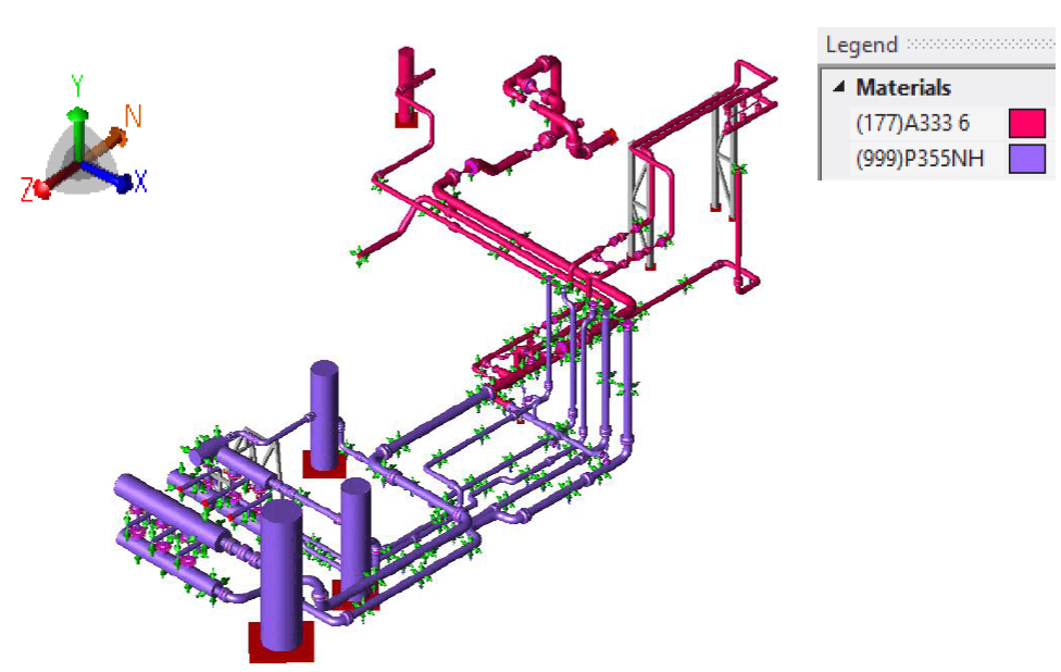
A detailed model of the Q8 Terminal piping system was created using CAESAR II, integrating all relevant geometric, material, and boundary condition data. The model spanned the entire compressor train, including upstream and downstream vessels, pulsation bottles, separators, air coolers, and all associated piping.
Equipment nozzles, a frequent source of localized stress, were represented using detailed finite element models developed in NozzlePRO and 661PRO for air coolers. The model geometry and material specifications were derived directly from as-built drawings, site measurements, and updated documentation from the site visit, ensuring that key details—including support types, support locations, and connection geometries—reflected the actual installation rather than design intent or legacy documentation.
Support System Representation
Special attention was given to the modeling of the support system. The compressor station’s piping, subject to both ASME and EN code requirements due to material spec breaks, included a combination of traditional and clamp-type supports. Clamp-type supports, in particular, were modeled with a realistic representation of their axial frictional restraint based on bolt torque and interface friction coefficients, as determined through both documentation and field measurement.
The inherent uncertainties in frictional restraint were addressed by adopting typical values, providing a conservative yet practical approach to load path prediction. Rigid vertical and lateral restraints were implemented where appropriate, and adjustments from the site visit—such as the removal or relocation of guides and the addition of structural steel supports—were incorporated to mitigate previously observed high-stress concentrations.
Component Flexibility and Connection Evaluation
The model incorporated detailed representations of component flexibilities, including branch connections, bends, and reinforced tees, with Stress Intensification Factors (SIFs) computed per ASME B31J. Gusseted connections at pressure safety valves were modeled in detail to capture their reinforced behavior.
All vessels and air cooler header boxes were included in the flexibility analysis, with FEA-derived stiffness values improving the accuracy of load transfer predictions at these critical interfaces. Material properties for all components were assigned based on project documentation and, where unspecified, conservative assumptions were made using standard carbon steel properties with corrosion allowances reflecting the most recent inspection data.
Process and Environmental Loading Conditions
The assessment encompassed a comprehensive range of loading scenarios, including static and dynamic operating conditions, hydrostatic test loads, thermal expansion and contraction, and wind loading. Design and operating pressures and temperatures were assigned based on isometric and vessel data, with adjustments made for sections that were derated to alleviate excessive nozzle or flange loadings. Environmental wind loads were included for all outdoor piping, modeled in four principal directions, and applied as occasional loads per code requirements. This ensured that the system’s response to extreme weather events was adequately captured.

Analytical Approach and Load Case Development
A robust set of load cases was defined to capture the full range of operational, test, and environmental conditions. These included sustained and alternate sustained cases, various operating scenarios at minimum and maximum pressures and temperatures, wind-induced loadings, hydrotest conditions, and thermal expansion ranges.
The use of alternate sustained cases was validated and found to have negligible impact on the results, supporting the conservative approach adopted. Flange and nozzle checks were systematically performed for all relevant cases, ensuring compliance with code limits and highlighting any areas of potential overstress.
Results: Pipe Stress, Flange Loading, and Nozzle Loads
The static stress analysis confirmed that all piping stresses remained within the allowable limits specified by ASME B31.3 and EN13480, substantiating the mechanical adequacy of the system under all considered load cases.
Flange loading was initially a concern: Nineteen out of 124 flanges exceeded limits when assessed using the traditional Kellogg equivalent pressure method. However, by incorporating the Koves factor—which acknowledges the conservatism of the Kellogg method regarding bending-induced face rotation—the number of non-compliant flanges was reduced to two. These two flanges, when further analyzed using a detailed ASME VIII Division 1 Appendix 2 methodology, were deemed acceptable, with maximum relative loading observed at 118% of the rated flange pressure before this advanced analysis.
Nozzle load assessments for all vessels, pulsation bottles, separators, and air coolers were performed using FEA-derived allowable loads. All equipment nozzles were verified to be within acceptable load limits, consistent with the structural integrity criteria for each interface. The integration of up-to-date support and connection data from the site visit was instrumental in achieving these results, particularly for nozzle assessments at locations where previous documentation had been incomplete or ambiguous.
Mitigation Measures and Model Refinement
Several targeted mitigation measures were implemented based on observed stress concentrations and the results of the initial analysis. These included increasing the fidelity of gusseted PSV connections, explicitly modeling air cooler connections, integrating additional steel structures for support, and relocating or removing specific supports to optimize load distribution. Selected sections of the system were also derated to further reduce localized stresses. These refinements, guided by both analytical results and field observations, were essential for achieving a robust and compliant system design.
Conclusions
The stress assessment of the Q8 Terminal compressor station’s piping system, underpinned by detailed site verification and model augmentation, demonstrates full compliance with relevant piping codes and mechanical integrity requirements. All static pipe stresses and nozzle loads are within allowable values. Flange loads, initially flagged by traditional methods, were confirmed to be acceptable following advanced assessment techniques. The approach adopted ensures that the system is fit for purpose, with minimal risk of mechanical failure or non-compliance.