
The client is operating multiple ammonia plants with similar cooling water systems made of GRE. Last year, failures were discovered in buried GRE components—specifically, an elbow and a tee—at one of the older plants. A surge analysis conducted by Dynaflow Research Group revealed that these failures were due to an unfavorable piping layout at the failure location, leading to high pipe stresses. Consequently, the client has engaged DRG to perform a static stress and surge analysis on a recently commissioned plant, even though it has not yet encountered any issues. This proactive approach aims to identify and mitigate potential stress-related failures in the GRE piping systems.
Stress Analysis
The piping in the plant is supplied by Future Pipe Industries (FPI) and is part of the Wavistrong series. This piping features a winding angle of 63°, which is higher than the more common 55°. The increased winding angle means that the glass fibers are oriented more towards the hoop (circumferential) direction, enhancing hoop strength but resulting in relatively lower axial strength. With this information, the stress envelope of the material can be defined to model the pipe stress in CAESAR II.
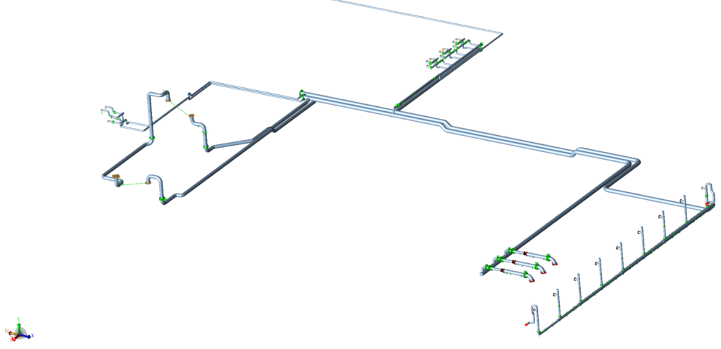
Figure 1 | The CAESAR II stress model.
Because the majority of the cooling water system is buried, a soil model was implemented according to the American Lifelines Alliance soil model standard. Soil settlement was not considered in this analysis. In addition to the stress analysis, flange and nozzle checks were conducted.
The stress analysis revealed that the system fails to meet the ISO 14692 design standard for Glass Reinforced Epoxy piping. It was found that the system is too rigid and includes numerous sections where guide supports are placed too close to elbows, multiple axial stops are present in straight pipe sections, and expansion loops are too small to provide the required flexibility. Moreover, the design pressure of the system (125 psig) exceeds the pressure class of the piping (116 psig). Combined with bending effects, this resulted in excessive stresses reaching up to 180% of the allowable values.
In the original configuration, the majority of the nozzle loads were below their allowable limits, except for one nozzle in Unit 103. It was observed that the nozzle loads remained largely unchanged even after all mitigation measures were incorporated.
Surge Analysis
For the surge analysis, the stress model was exported from CAESAR II into the surge analysis software package BOSfluids a specialized software package for surge and transient flow analysis in piping systems. The only additional information required in the BOSfluids model were the boundary conditions at the pump suction side and at the cooling tower. Additionally, the pump settings had to be configured to represent the system’s operating conditions.

Figure 2 | Routing of the surge model.
The system is equipped with three different pumps that can be operational at the same time. Four different surge scenarios have been analyzed:
- Pump trip: 2 pumps are running at normal settings, while 1 pump trips.
- Pump start-up: 1 pump is on stand-by while 2 pumps are started simultaneously.
- Pump switchover: 2 pumps are running. 1 of them starts spinning down, while the stand-by pump is being started.
- Closure of flow control valve FV8008: the valve is closed in 120 seconds.
During the pump trip scenario, the highest pressure in the system was found to be 96.5 psig, which is below the system’s design pressure of 125 psig. The highest unbalanced forces were observed in the header connecting the three pumps, with a magnitude of 17,000 lbf (75.6 kN). Since the header is a 56-inch buried pipe, the soil provides sufficient restraint, making the effect of these unbalanced forces negligible.In the pump start-up scenario, a higher pressure peak of 110 psig was measured directly at the pump discharge side. The highest unbalanced forces were again observed in the buried pipe header, measuring 10,200 lbf (45 kN). Similar results were noted during the pump switchover scenario, which involves operating pumps in parallel.
Finally, the valve closure scenario did not pose any risk to the system because the valve was closed slowly over 120 seconds. Slow valve closures minimize pressure surges (water hammer) by allowing gradual changes in fluid velocity, thereby preventing sudden pressure increases.
Conclusions And Recommendations
- The analysis revealed that many parts of the system lack adequate flexibility, particularly near nozzles and bends in the buried pipe sections. Additionally, the system is excessively constrained in certain areas due to the placement of supports and restraints.
- The system’s design pressure of 125 psig is high relative to the pressure class of the pipes used, which is rated at 116 psig. This leaves minimal allowance for additional stresses arising from longitudinal effects such as bending and thermal expansion. Therefore, reinforcement measures are required to reduce stresses to stay below the allowable limit according to the ISO 14692 design code.
- The surge analysis indicated that the highest pressures resulting from various transient scenarios remain below the system’s design pressure of 125 psig.
- The highest unbalanced loads during various transient scenarios occur in buried piping, where these effects are negligible.
- To address some of the challenges mentioned above multiple mitigation strategies were recommended involving the support arrangement, with the main goal of adding more flexibility to the system.