
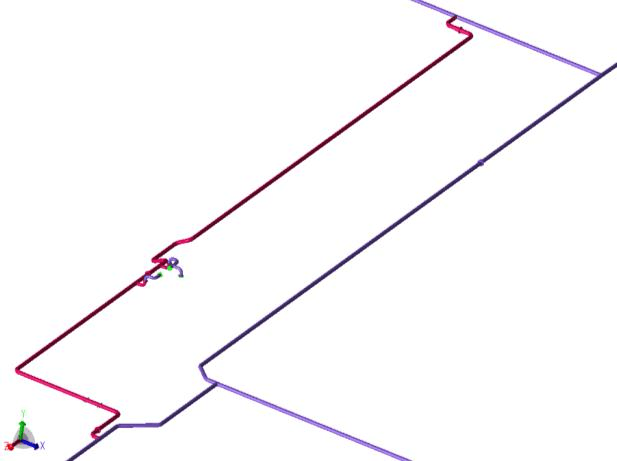
Nine underground GRE firewater systems, 77 stressed isometrics in total, were analysed in CAESAR II against the ISO 14692 allowable stress envelopes, with soil-pipe interaction modelled to the American Lifelines Alliance (2001) soil model. Modifications included a support bracing, polystyrene foam, NBR gasket stiffness limits and additional laminate for a 4 mm minimum thickness, and the Fx load at one nozzle (30.7 kN against 20.5 kN) remains open until the continuation piping is analysed.
An existing underground firewater network at an LNG facility in Norway was extended with new piping in GRE Wavistrong EST 20 (glass reinforced epoxy, GRE). The existing network is also fibreglass. The material has an elastic modulus of 20,500 MPa in the hoop direction and 10,500 MPa in the axial direction, and a long-term uni-axial strength of 32.5 MPa. The extension was analysed for a design pressure of 19.2 Barg and a hydrotest pressure of 28 Barg, over a design temperature range of -14 °C to +50 °C with an installation temperature of +15 °C. The analysis covered nine systems and 77 stressed isometrics in total, including DN750 piping. Where pipe stresses or flange loads exceeded the allowable values, modifications were proposed and the system was re-analysed.
DESIGN BASIS
Pipe material | GRE Wavistrong EST 20 |
Elastic modulus, hoop | 20,500 MPa |
Elastic modulus, axial | 10,500 MPa |
Long-term uni-axial strength | 32.5 MPa |
Design pressure | 19.2 Barg |
Hydrotest pressure | 28 Barg |
Design temperature range | -14 °C to +50 °C |
Installation temperature | +15 °C |
Systems / stressed isometrics | 9 / 77 |
Software and standard | CAESAR II; ISO 14692 |
Load Cases, Soil Model, Continuation Piping and Flange Checks
The static stress analysis was carried out in CAESAR II, and the calculated stresses were compared with the allowable stress envelopes of ISO 14692. Four load cases were assessed: hydrotest (water-filled weight plus hydrotest pressure), hot operation (weight, design pressure and hot design temperature), cold operation (weight, design pressure and cold design temperature) and a sustained case (weight and design pressure). The envelopes were constructed with part factors of 0.67 for sustained, 0.83 for operational and 0.89 for occasional and hydrostatic loads. Stress intensity factors for fittings were applied in accordance with ISO 14692, and all DN600 and DN750 elbows were modelled as mitred elbows.
LOAD CASES
Case | Load combination |
Hydrotest | Water-filled weight plus hydrotest pressure |
Hot operation | Weight, design pressure and hot design temperature |
Cold operation | Weight, design pressure and cold design temperature |
Sustained | Weight and design pressure |
The pipe is buried in 8 to 16 mm crushed rock backfill, and the soil-pipe interaction roughly resembles the behaviour of dense sand. It was modelled with the American Lifelines Alliance (2001) soil model, using a friction angle of 35°, a soil density of 1,900 kg/m3, a coating factor of 0.6 (typical for GRP pipe) and a cover depth of 1,200 mm to the top of the pipe. The cover depth determines the soil resistance acting on the pipe, which affects the pipe stresses. No significant settlements were expected, so settlements were not included.
SOIL MODEL PARAMETERS
Backfill | 8 to 16 mm crushed rock |
Friction angle | 35° |
Soil density | 1,900 kg/m3 |
Coating factor | 0.6 |
Cover depth to top of pipe | 1,200 mm |
The new piping is referred to as scope piping. Piping beyond the scope piping, such as the existing network and the connecting above-ground piping, was included in the models where necessary as continuation piping, to provide overlap and accurate boundary conditions. Continuation piping was not analysed for stress. Flange loads were checked with the CAESAR II flange check: the external axial force (set to zero when compressive) and bending moment at the flange were converted into an equivalent internal pressure, added to the internal pressure, and compared with an allowable pressure equal to twice the pressure class, including the part factor for the load case.
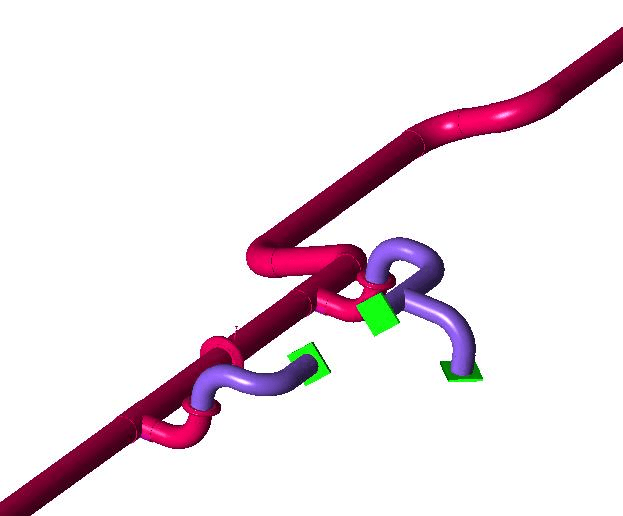
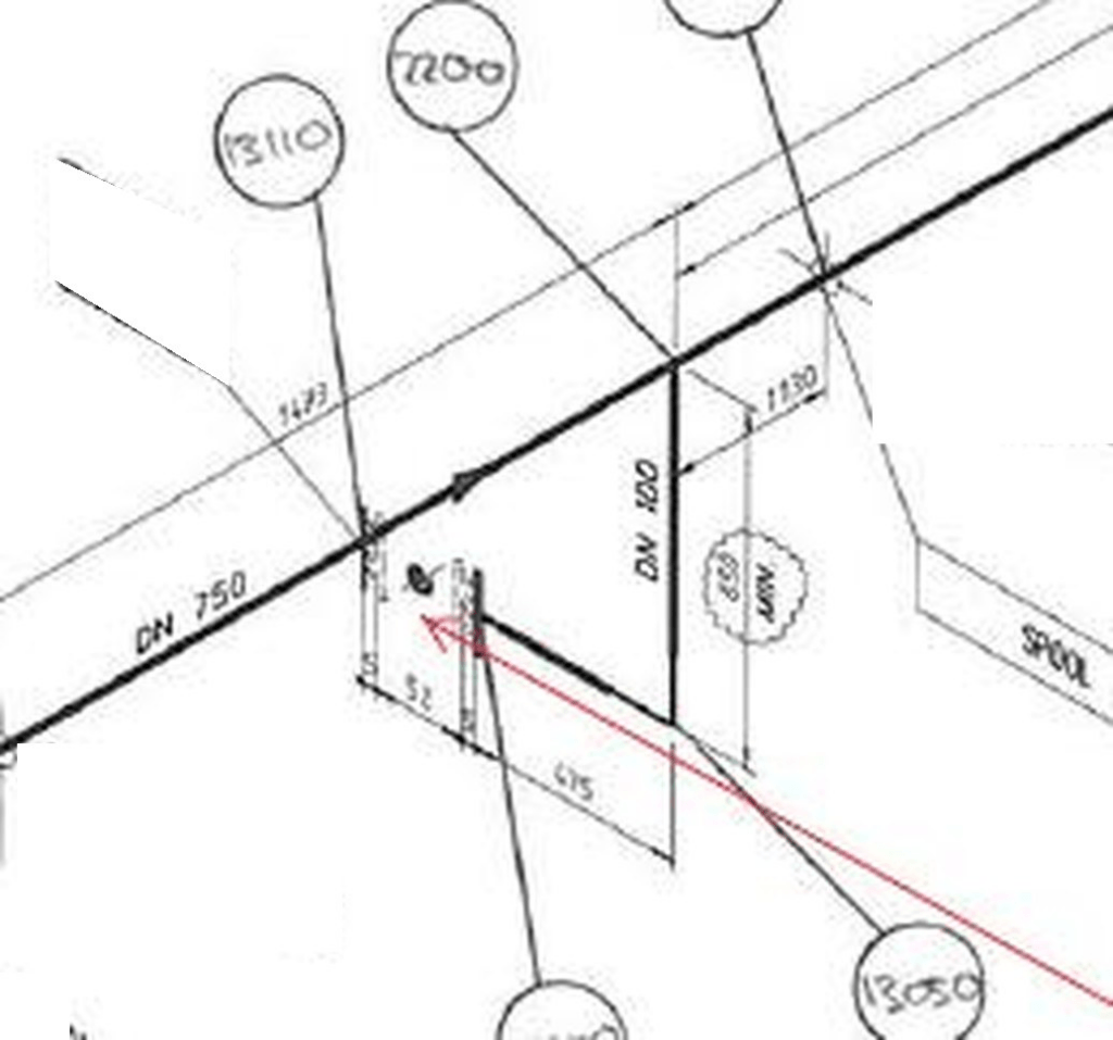
Bracing, Foam, Gasket, Laminate and Support Modifications
The modifications are marked up on the isometrics. In system 1, a support bracing was introduced for a DN100 valve from the DN750 main line. Steel rods or beams, or equivalent, run from clamps around the DN750 line to the valve. The bracing improves the resistance of the branch to handling loads and other unforeseen loads on the valve. It is used instead of a standard support under the line, because friction under such a support prohibits movement of the valve and can result in high stresses when the main line expands under pressure and temperature.
The DN250 branch pipe in system 2 was a critical location at the tee. Polystyrene foam (1.5 m) was applied right after the valve pit exit to add flexibility and reduce the stress. When system 4 was modelled with a more accurate continuation of the piping, high stresses occurred at this branch even with the polystyrene. In addition to the polystyrene, the maximum stiffness of the NBR rubber gasket sealing the DN250 branch at the manhole-to-soil transition was limited to 1.5 million N/m. Similar limits were set in system 9, where high stresses occurred at two manholes: 12 million N/m for the DN300 pipe at node 5220 and 6 million N/m for the DN150 pipe at node 11560. Gasket stiffness can be approximated from the pipe outside diameter, the elastic modulus of the rubber, and the gasket width and thickness. The true stiffness must be checked and should not exceed these limits.
MAXIMUM NBR GASKET STIFFNESS AT MANHOLE-TO-SOIL TRANSITIONS
System | Pipe | Location | Maximum stiffness |
2 and 4 | DN250 | Branch at manhole-to-soil transition | 1.5 million N/m |
9 | DN300 | Node 5220 | 12 million N/m |
9 | DN150 | Node 11560 | 6 million N/m |
In system 4, additional laminate was applied from the flange to the manhole exit on the DN150 piping inside the manhole leading to the hydrants, to ensure a minimum pipe thickness of 4 mm. In system 6, rest supports were introduced underneath the flanges of one DN50 spool and two DN100 spools. In system 7, a concrete cradle support in a valve chamber acted as a three-way stop. It caused loads of up to 24 kN on the pipe, and it is doubtful that the pipe would stay in the cradle. The results show that no stress problems are introduced when the cradle is changed to a rest only (+Y) support, so the cradle was marked up as a rest only support.
For horizontally orientated valves in systems 3, 4 and 9, a rest support and a guide (lateral) support are good practice, mainly to improve resistance to handling loads. In system 4 the valve in the DN250 branch from system 2 is the exception, because these supports would restrict pipe movement too much and result in high stresses. In system 9, a guide is not used where thermal expansion prohibits it. No modifications were required in systems 5 and 8, and no critical area was identified in system 3.
Nozzle Load, Above-Ground Assumptions and Verification Points
The loads on the two deluge skid nozzles in system 1 were compared with the maximum allowable values. All components were within the allowable values except the Fx load component at one nozzle, which was 30.7 kN against an allowable 20.5 kN. This load is attributed to the truncation of the model at the skid interface, so a modification of the new GRE piping does not seem to be required. Adjusting the continuation piping is proposed and must be considered when it is analysed. With the whole continuation modelled, the additional flexibility is expected to lower the load at this nozzle, in line with the other nozzle. No final conclusions can be drawn yet, because the received Navisworks model does not show how the piping continues downstream of the anchor.
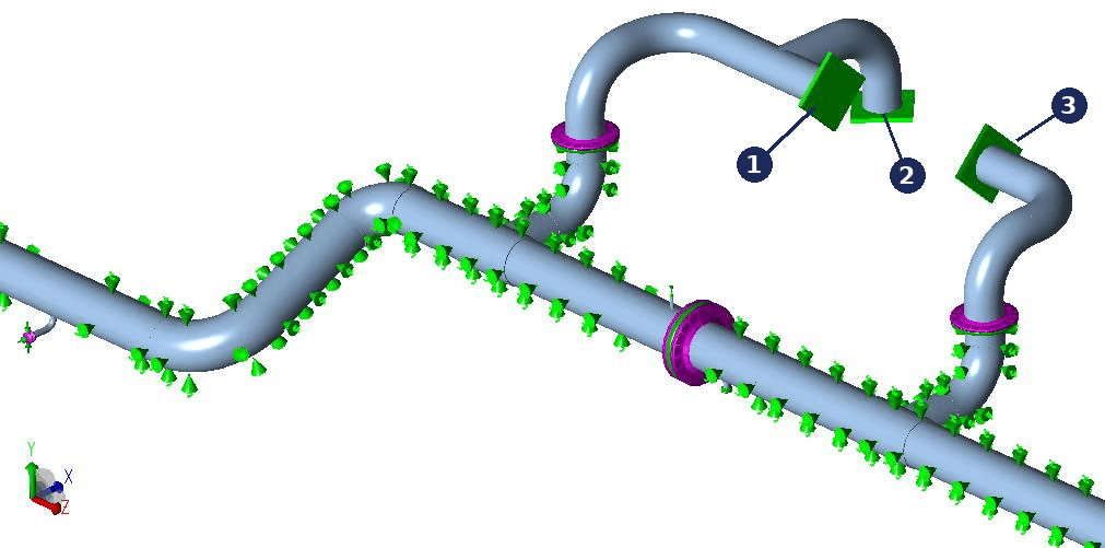
- Nozzle with the Fx load component above its allowable (30.7 kN against 20.5 kN)
- Anchor at the model truncation
- Nozzle with all load components within the allowable values
Assumptions on the supports of the connecting above-ground piping had to be made, because not all support details were available at the time of analysis. These assumptions affect the stress levels in the analysed GRE piping, and it is advised that they are verified before production of the pipe starts.
In system 7, an estimate using approximate dimensions showed overstress at an equipment nozzle in the above-ground GRE piping, which is outside the analysed scope. The stress can be reduced either by extending the above-ground horizontal run by about 500 mm and moving the equipment correspondingly, or by adding an elbow in the horizontal plane. A proper assessment based on the actual geometry is advised, and this advice is not marked up on the isometrics.
In system 9, pipes shown as parallel in the Navisworks model intersect when the isometric dimensions are used. The Navisworks model shows a separation of about one pipe diameter, which is assumed to be correct and sufficient. A significantly smaller separation might pose problems for stress and installation, and verification is requested. Some supports appear on the pit detail drawings but not on the isometrics. The modelling followed the isometrics, which are taken as ruling where the drawings differ. At two positions the supporting on the detail drawings gave better results, and it was adopted in the analysis and marked up.
Frequently Asked Questions
Why is a bracing used instead of an under-pipe support on a small-bore GRE branch?
Friction under a standard support below the line prohibits movement of the branch and can result in high stresses when the header expands under pressure and temperature. A bracing from clamps around the header, using steel rods or beams or equivalent, supports the branch instead and improves its resistance to handling loads and other unforeseen loads on the valve. In system 1 this was applied to a DN100 valve from the DN750 main line.
Which load cases are assessed in an ISO 14692 stress analysis of buried GRE piping?
Four load cases were assessed: hydrotest (water-filled weight plus hydrotest pressure), hot operation (weight, design pressure and hot design temperature), cold operation (weight, design pressure and cold design temperature) and sustained (weight and design pressure). The allowable envelopes were constructed with part factors of 0.67 for sustained, 0.83 for operational and 0.89 for occasional and hydrostatic loads.
How should a nozzle load above its allowable be treated when the model is truncated at the equipment interface?
In system 1 the Fx component at one deluge skid nozzle was 30.7 kN against an allowable 20.5 kN. The load is attributed to the truncation of the model at the skid interface, so a modification of the new GRE piping does not seem to be required. Adjusting the continuation piping is proposed and must be considered when it is analysed; with the whole continuation modelled, the additional flexibility is expected to lower the load at this nozzle. No final conclusions can be drawn yet, because the received Navisworks model does not show how the piping continues downstream of the anchor.