
At a refinery, instrument air is supplied by three Atlas Copco compressors. Two are motor driven; the third is driven by a Coppus RHLA-24 steam turbine commissioned in 2008. Two months after start-up, a plain bearing malfunctioned. The turbine was overhauled and reassembled at site in August 2009, after which the unit was aligned in both cold and hot conditions. Hot alignment was unsuccessful.
In the majority of cases, bearing problems and misalignment result from turbine casing deformation, and the deformation results from nozzle loads imposed by the connected piping. Attention therefore focused from the outset on the steam supply and exhaust lines connected to the turbine. The client requested Dynaflow to investigate the root cause and advise an improvement to the system.
CAESAR II Model of the Turbine Inlet and Exhaust Piping
The connected piping was remodelled in CAESAR II. The model covers the 3 inch inlet line and the 10 inch exhaust line up to the pipe rack, with a portion of the rack continuation included for overlap. Ancillary connections of 1 inch and below were assessed as negligible relative to the main piping and nozzle sizes. The model was constructed from the supplied stress isometrics and support details, with the turbine thermal growth represented as imposed displacements at the inlet and exhaust nozzle flanges. Nozzle loads were checked against NEMA SM 23. The pipe material is A106 Gr. B.
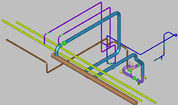
The initial model, built from the stress isometrics and the input echo of the original analyst’s CAESAR II model, passed the NEMA SM 23 check at 95% of the allowable. A sensitivity check of the model assumptions then revealed a potential mistake: the imposed hot displacements of the inlet and exhaust nozzles did not match the manufacturer’s information. With the manufacturer-specified displacements, the nozzle load check gave 122% of the allowable for SMY and 103% for SMZ.
While the operational problems were being investigated, the client and the original analyst found that the maximum exhaust operating temperature was 288 °C (turbine no load), against the 180 °C operating temperature applied in the original stress calculations. The manufacturer’s displacement values could not be verified or traced back to starting parameters, so Dynaflow determined the nozzle displacements with expansion coefficients from RToD D 0105. The mean temperature of the turbine set the horizontal displacement for each analysis case, and a pedestal base temperature of 40 °C was used for the vertical displacement.
Guide Support Friction and Tie Rod Vibration
More detail was then included in the model of three supports to simulate their function and flexibility: the 2 mm upward gap in the eye-plate of special pipe support 010, the as-built supporting steel of special support 011, and the as-built supporting steel and rotational limitation of the 1 mm gap guide of support PS-64795-021. The nozzle loads were above the NEMA SM 23 allowable, at about 114% of it.
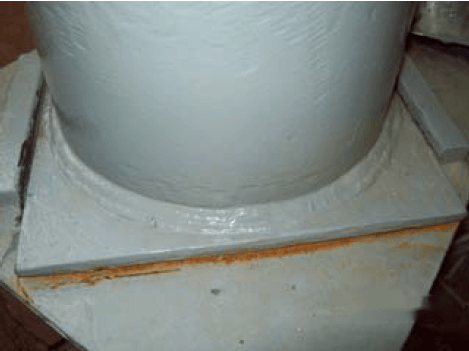
A site visit showed that, for the cold piping, the special 45 degree guide support under the dummy at support PS-64795-021 had not returned to its original cold position. Friction at the support was apparently preventing the required easy sliding. The 1 mm gap was filled with dirt, and the dummy base plate was stuck in the rotated position. In the model, two guide functions replaced the rotational stop to represent the relatively long guide strips, and friction was added to the horizontal guide function. The exhaust nozzle bending moment was approximately 11 kNm, and the nozzle load check gave 387% of the NEMA SM 23 allowable. The 10 inch 150# flange was also overloaded.
Two primary causes of the nozzle overload were identified. Friction at support PS-64795-021 exceeded the anticipated figures and is a primary cause of the alignment issues. Once the friction was corrected in the model, the flexibility of the existing routing was insufficient and the exhaust nozzle loads exceeded the allowable.
Vibration of the tie rods of support 010 was reported during turbine and compressor operation. A dynamic analysis showed a half sinusoidal vibration mode of the rods at 49.5 Hz, which equals a turbine speed of 2970 rpm. The rod vibration is apparently related to mechanical resonance.
Exhaust Piping Reroute and NEMA SM 23 Assessment
A preliminary verification of the option of replacing the guide at support PS-64795-021 with a modified guide function with less friction, and the rest support with a rigid pipe hanger (no friction), gave 120% of the NEMA SM 23 allowable, still not within the allowable values. In cooperation with the client, a complete overhaul (rerouting) of the exhaust connection was concluded to be the best way forward to solve the overload issues. The rerouting and adjusted support configuration has to minimise friction at the supports close to the exhaust connection and provide additional flexibility to decrease the exhaust nozzle loads.
The revised support configuration includes restraints to minimise the loads on the turbine exhaust nozzle. A spring hanger at node 55 reduces the dead load on the nozzle, and a pipe hanger at node 5070 minimises the torsion moment on it. A spring hanger at node 5120 supports the loop against sag from vertical thermal expansion. An assembly of two rigid struts at node 5140 restrains the loop in the north-south direction and limits its bending. Dummy supports at nodes 80 and 170 minimise the influence of the downstream piping on the exhaust nozzle; node 80 has rest, stop and guide functions and node 170 has rest and guide functions.
NEMA SM 23 leaves room for discussion on the location of the resolution point, which it defines as lying at the centreline of the exhaust connection. In the first method (Dynaflow’s interpretation), the point is at the crossing of the flange facing of the exhaust connection and its centreline. In the second method (the original analyst’s interpretation), it is at the crossing of the surface through the exhaust centreline parallel to the vertical axis and the turbine shaft. All cases were assessed by both methods for the revised configuration, and the table gives the maximum percentage of the allowable for each case.
| Case | First method | Second method |
|---|---|---|
| 1 | 75% | 57% |
| 2 | 67% | 52% |
| 3 | 78% | 67% |
| 4 | 59% | 40% |
| 5 | 84% | 63% |
| 6 | 82% | 58% |
Cases 5 and 6 are imaginary cases: case 5 is case 1 with the manufacturer-supplied thermal displacements, and case 6 is case 1 with the original analyst’s extrapolated displacements. Of cases 1 to 4, the maximum is 78% for case 3 by the first method and 67% by the second. Case 3 is at design temperature with flow through the HP bypass. The reroute and revised support configuration resulted in increased flexibility and decreased loads on the turbine nozzle.
Probable Cause of Steam Turbine Misalignment
The intermediate conclusion from the analyses is that the support arrangement of the turbine outlet piping creates nozzle loads above the allowable, and that these loads generate turbine casing strain that affects the alignment of the turbine. The exhaust piping in its present layout is most probably responsible for the misalignment problems. The client tested the stiffness of the turbine supporting frame, which had been questioned. The test results were dissatisfactory and are not discussed further in the report.
Frequently Asked Questions
How does connected piping affect steam turbine alignment?
Nozzle loads imposed by the connected piping deform the turbine casing. In the majority of cases, bearing problems and misalignment result from that casing deformation. For this reason the analysis started with the steam supply and exhaust lines connected to the turbine.
What did the NEMA SM 23 check give for the rerouted turbine exhaust?
Of cases 1 to 4, the maximum was 78% of the allowable, for case 3 (design temperature with flow through the HP bypass), by the first method. The second method gave 67% for the same case. The two methods differ in where they place the resolution point at the exhaust connection. Cases 5 and 6 are imaginary cases and were excluded from the maximum. They gave 84% and 82% by the first method, and 63% and 58% by the second.
What nozzle load did a jammed guide support produce on a steam turbine exhaust?
The model gave an exhaust nozzle bending moment of approximately 11 kNm, which is 387% of the NEMA SM 23 allowable. This model had two guide functions in place of the rotational stop and friction added to the horizontal guide function. It reflected a site visit finding that the 45 degree guide support had not returned to its original cold position, with the 1 mm gap filled with dirt. The 10 inch 150# flange was also overloaded.