
A BOSfluids surge analysis and slug impact calculation of a 12-inch steam start-up line gave maximum unbalanced forces of 1.32 kN, 1.3 kN and 3.2 kN for three surge scenarios, and 16.5 kN and 23 kN for 7 m and 10 m slug impacts on the pressure control valve. CAESAR II dynamic stresses of 92.0 MPa and 88.8 MPa were below the 137 MPa occasional allowable, and the combined load on the three-way stop was more than a regular support shoe can support.
Steam Start-Up Line Operating Context
A facility will use steam to enhance oil production. During the start-up of steam production, a 12-inch line connected to a start-up vessel is initially used for the steam and water flow. The vessel receives this mixture until the steam reaches its target quality, and from that moment the start-up line is closed and the steam is redirected towards the injection points. The 12-inch size of the line, with the corresponding two-phase flow, may induce high loads on the start-up vessel. The analysis predicted the unbalanced pipe loads in the steam start-up line during start-up and during a steam dump scenario, in which surge loads and slug formation may occur.
Surge Model Scope and Three Scenarios
The scope covered the steam start-up line and the start-up vessel. To improve the accuracy of the results for the start-up line, the surge model also included part of the main header and the steam lines from and in the boilers. The distance from the evaporator to the start-up vessel, and the volume of the piping between them, influence the pressure transients, so that piping was modelled from the available drawings. The steam line details in and from the boilers were neglected, so the accuracy of the calculated unbalanced loads in the boiler coil piping and in the steam line to the tie-in of the start-up line is limited.
Three scenarios were analysed. In the first, water at 26 bara is in the line and the pressure control valve opens until a mass flow of 103.5 kg/s is reached. In the second, the normal steam start-up sequence, steam forms to a dryness fraction of 75%, the line is pressurised from 26 bara to 142 bara, and the pressure control valve closes so that flow enters the injection area at 103.5 kg/s. In the third, a sudden steam dump, the flow rate in the injection area increases to 150 kg/s and water and steam are dumped into the start-up vessel.
Surge Results, Flow Regime and Slug Load Basis
The scenarios were run in BOSfluids, which calculates the flow and pressure transients and determines the unbalanced loads from them. An unbalanced load occurs between a pair of elbows when the pressure in one elbow differs from the pressure in its complement, and its magnitude and time history depend on the length of pipe between them.
| Scenario | Mass flow | Maximum unbalanced force | Maximum pressure |
|---|---|---|---|
| Water start-up | 103.5 kg/s | 1.32 kN | 28 barg |
| Steam start-up | 103.5 kg/s | 1.3 kN | 147 barg |
| Steam dump | 150 kg/s | 3.2 kN | 147 barg |
Flow regime was assessed with the theories of Baker, Hewitt and Taitel, using the Lockhart-Martinelli approach for the actual gas and liquid velocities. The Baker map predicts a slug flow regime when steam generation starts, changing to annular flow as more steam is generated. The Taitel and Dukler map gives approximately the same results and predicts slug flow more clearly at the start of steam generation. For horizontal pipelines, slugging is likely up to a steam fraction of 10 to 15%. Although slugging at the high end of the vapour mass fractions is highly unlikely, it is recommended to use the maximum predicted slug load independent of the flow regime. This maximum, a momentum force on an elbow at the high end of the vapour mass fractions, is 28 kN and was used as the elbow load input for the dynamic stress analysis. Slug loads may increase if the mass flow rate exceeds 103.5 kg/s. In the dump scenario the flow regime lies well within the annular flow map, and no slugs are predicted.
Valve Slug Impact and Nozzle Flashing Force
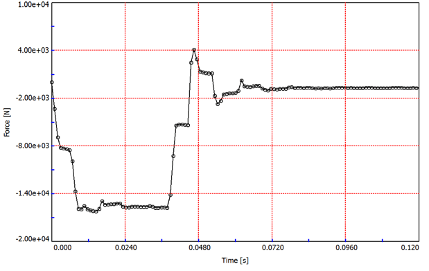
A slug can load piping by several mechanisms, two of which are momentum change as it passes an elbow and impact on a partially closed valve, which is a very fast phenomenon. BOSfluids is a single-phase model and cannot model slugs directly. The impact on the pressure control valve was therefore modelled by establishing a steady state in which a pipe length equal to the slug length is filled with liquid at the slug velocity, and closing the valve over the slug impact time of 0.0375 s. Slugs of 7 m and 10 m length were evaluated, each at 8 m/s and a density of 754 kg/m3, based on the theory of Taitel and Dukler. The model inputs included a vapour fraction of 0.1, a mass flow rate of 103.5 kg/s and a pipe inner diameter of 266.7 mm.
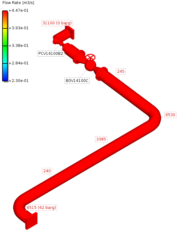
For a slug passing an elbow, the mass flux that sees the velocity change is proportional to the fluid velocity. For a slug decelerated by the valve, the force is determined by both the impact time and the wave speed in the fluid. The wave speed is two orders of magnitude larger than the fluid velocity, so the impact load is much higher than the elbow force of a slug moving at the same velocity.
The flashing load on the pressure control valve was checked using API 520 for a regular scenario at 103.5 kg/s and a dump scenario at 150 kg/s, each at 75% steam and 25% water. The force on the vessel nozzle is 62.1 kN in the regular scenario and 90 kN in the dump scenario. The 90 kN force is balanced by stresses in the vessel wall and is not transferred to the vessel foundation.
Slug Impact Results and B31.1 Dynamic Stress Assessment
The 7 m slug gave a maximum unbalanced force of 16.5 kN on the pipe segment that contains the pressure control valve and a maximum pressure of 66.2 barg. The 10 m slug gave a maximum unbalanced force of 23 kN on the pipeline upstream and perpendicular to the pressure control valve pipeline and a maximum pressure of 69.5 barg. The 28 kN elbow force and the slug impact force, with a maximum of 23 kN, were applied in a CAESAR II dynamic stress model. The static 90 kN flashing force acts directly on the nozzle and is not included in the dynamic results.
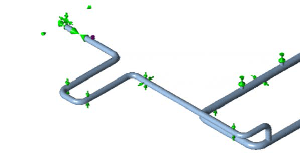
An earlier revision of the analysis assumed a rigid tank nozzle. A rigid connection causes reaction forces that limit the design of the nozzle wall thickness. Including the flexibility of the nozzle connection transfers more of the load to neighbouring supports and reduces the loads on the nozzle. The flexibilities were determined by finite element analysis in NozzlePRO, and most of the flexibility comes from the semi-elliptical head. The nozzle and head dimensions were not final and were taken as upper limits of thickness, so a lower actual wall thickness gives a conservative result.
The dynamic stresses were assessed as occasional stresses, combined with the static sustained stresses at the operating pressure. The B31.1 hot allowable stress is 114 MPa at 162 barg and 349 °C. With the occasional factor of 1.2 specified by the client, the occasional allowable is 137 MPa. The maximum stress is 92.0 MPa for the 7 m slug and 88.8 MPa for the 10 m slug, both below the 114 MPa hot allowable and the 137 MPa occasional allowable.
| Slug length | Maximum unbalanced force | Location of maximum | Maximum pressure | Maximum stress |
|---|---|---|---|---|
| 7 m | 16.5 kN | Pipe segment containing the pressure control valve | 66.2 barg | 92.0 MPa |
| 10 m | 23 kN | Pipeline upstream and perpendicular to the pressure control valve pipeline | 69.5 barg | 88.8 MPa |
Three-Way Stop and Support Shoe Loads
The modifications to the original model were a shortened loop, an added guide that creates a three-way stop, and the nozzle flexibility. They reduced the nozzle loads and the maximum stresses. The static restraint loads are already high, and the combined static and dynamic load on the three-way stop is more than a regular support shoe can support.
Steam Start-Up Line Slug and Surge Analysis FAQ
How large were the unbalanced forces in the three surge scenarios?
The maximum unbalanced force was 1.32 kN for the water start-up, 1.3 kN for the steam start-up and 3.2 kN for the steam dump. The corresponding maximum pressures were 28 barg, 147 barg and 147 barg. All three scenarios were run in BOSfluids.
What load did a slug impact on the pressure control valve produce?
A 7 m slug at 8 m/s produced a maximum unbalanced force of 16.5 kN and a maximum pressure of 66.2 barg. A 10 m slug produced 23 kN and 69.5 barg. The impact load is much higher than the elbow force of a slug moving at the same velocity, because the wave speed in the fluid is two orders of magnitude larger than the fluid velocity. The elbow force used as input for the dynamic stress analysis was 28 kN.
Were the dynamic stresses within the B31.1 allowable?
Yes. The dynamic stresses were assessed as occasional stresses and combined with the static sustained stresses. The maximum stress was 92.0 MPa for the 7 m slug and 88.8 MPa for the 10 m slug, against a 114 MPa hot allowable and a 137 MPa occasional allowable at a factor of 1.2. The combined static and dynamic load on the three-way stop was more than a regular support shoe can support.