
Condensation and Steam Hammer in a Cold Steam Line
The analyses assumed steam at 380°C and 40 Barg entering a 36-inch high-pressure steam line with a pipe temperature of +5°C. Potential problems are anticipated at start-up because the steam condenses on entering the cold pipe. Steam remaining in the line during a plant stop may also condense, and insufficient drainage before restart leaves cold water at the lower locations. Two start-up cases were analysed: a dry, well-drained line and a line with retained cold water. Drawings were not available, so both cases used the pipe geometry from a CAESAR II model.
The superheated steam core loses heat to the cold pipe wall, and the steam layer in contact with the wall condenses. When the core has cooled to the saturation temperature, about 250°C at 40 Barg, condensation takes place on a larger scale. The condensed water starts a two-phase flow, which may locally enter the slug flow regime.
The dry-line case is assessed for slug loads. In the case with cold water, steam hammer may occur if the water is in the part of the line where slug formation may occur. In the slug regime, steam-filled areas are entrapped between liquid slugs. If an enclosed steam area between two slugs contacts the cold water, it might condense almost instantaneously and collapse. The two slugs bordering that area collide, and the collision generates a water hammer wave, called steam hammer because of its origin. Documented incidents exist in which the pressure exceeded the pipe capability in such a case.
Flow Regimes and Slug Load Results
The flow calculations place the start of film condensation about 110 m downstream of the entry, where the core steam temperature has fallen to saturation temperature. The condensate forms an annular film on the wall while fast steam flows in the core. From about 650 m downstream of the entrance the flow changes from annular to wavy and stratified, and about 50 m further it enters slug flow. These results carry an uncertainty margin, and each transition between regimes occupies a transition area.
Regime transitions were referenced to Taitel and Dukler (1976) and Baker (1954). The Taitel illustrations show an earlier transition to slug flow than the Baker flow maps. The first slug formation is likely at 12.5% steam quality, the steam mass fraction of the total flow mass. At that steam quality the calculated slug load is about 12.9 kN with an intermittency of about 25 s.
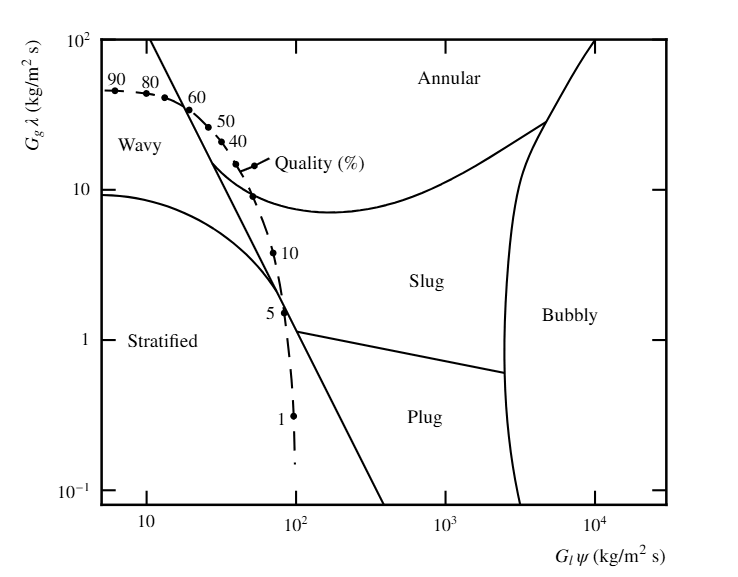
The slug flow regime for the condensing flow applies only to the last part of the line, about the second half of the developed length of about 1000 m in the CAESAR II model. The project data sheet mentions a total line length of 750 m. The CAESAR II analysis conservatively assumed that slug load conditions may occur downstream of node 1040, about 600 m downstream of the entrance, with flow in the direction of increasing node numbers. In reality the slug load decreases farther downstream as condensation continues, because the steam velocity is reduced, but the analysis applied a constant slug load. With this constant slug load, the maximum combined static and dynamic support load is around 100 kN. Pipe stresses during slug load impact are within allowable limits.
Steam Hammer Peak Pressure by Condensation Assumption
The steam hammer assessment ran in three stages. The maximum pressure generated during the collapse depends on the size of the slugs (the amount of collected water). Stages 1 and 2 used BOSfluids simulations of the collapse of the steam entrapped between two slugs, for several slug sizes. The impact velocity was determined and the peak pressures from the interaction of pressure wave reflections at the slug edges were calculated. The simulation is quasi one-dimensional, so the slug edges were taken as straight and perpendicular to the pipe centreline, which simplifies reality.
The maximum allowable pressure pulse without damage to the pipe is 158 Barg, based on the occasional cold allowable stress in the corroded condition. It is considered justified to base this limit on the cold allowable, since the phenomenon only occurs in a cold line. In both stages the pressure wave transmission coefficient from the liquid slug into the steam is about 2%, so 2% of the pressure pulse (3 Barg) is transmitted through the steam in the rest of the pipe.
Stage 1 assumed instantaneous condensation, which makes its results conservative. In reality condensation is not instantaneous, because the latent heat of the entrapped steam must be transferred to the cold water over a finite time. In stage 1 the pressure stays within the maximum allowable pressure for the pipe if the slug volume is less than 0.3 m³. If all undrained water in the line, generated during the plant stop by condensation, is assumed to collect in the slugs, the undrained water between two expansion loops must be less than 0.3 m³.
Stage 2 included direct contact condensation, using a typical Direct Contact heat transfer coefficient of 15 kW/(m²K), with papers by Hughes and Duffey given as reference. With this finite condensation rate, the pressure stays within the maximum allowable pressure if the retained undrained water between two expansion loops is limited to 1.5 m³. A volume of 1.5 m³ of condensed water at about 5°C corresponds to 75 m³ of saturated steam at 40 Barg and 250°C. For a pipe with an internal diameter of 0.841 m, that steam volume is the initial steam content of a 135 m length, which is more than the typical distance between two expansion loops.
| Stage 1 | Stage 2 | |
|---|---|---|
| Condensation assumption | Instantaneous | Finite, 15 kW/(m²K) |
| Undrained water between two expansion loops | Less than 0.3 m³ | Limited to 1.5 m³ |
| Maximum allowable pressure pulse | 158 Barg | 158 Barg |
| Transmission coefficient | About 2% | About 2% |
Unbalanced Loads From Steam Hammer Wave Propagation
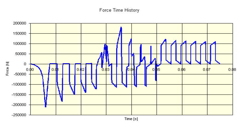
Stage 3 used the collapse of a 1.307 m slug with direct contact condensation. The pressure wave generated in the slug during collapse was determined, the time history of the transmitted wave in the steam was calculated, and the propagation of that wave through the line was simulated in BOSfluids. The wave generates unbalanced loads between elbow pairs, which in turn generate support loads. The pressure time histories and the unbalanced load time histories are similar at all locations indicated. The unbalanced load amplitude is about 200 kN and its duration is milliseconds.
Dynamic Load Factor and the Limit on Undrained Condensate
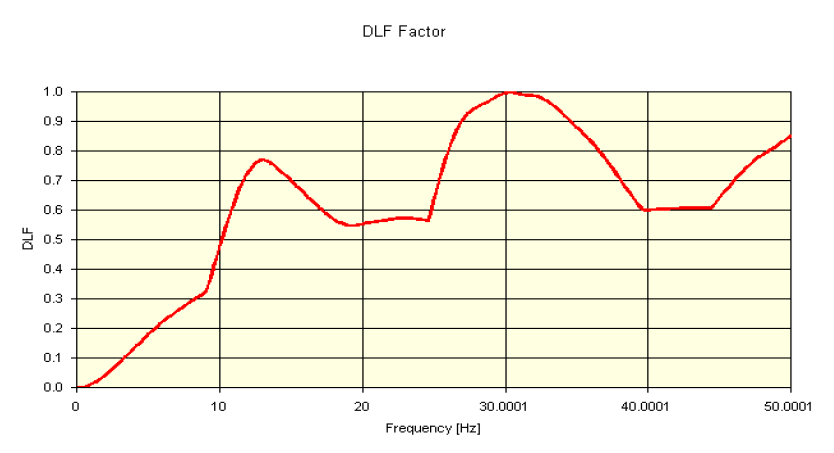
Because the load duration is milliseconds, the impact on a pipe line with a relatively large inertia was anticipated to be limited. A load response spectrum was calculated over 0 to 50 Hz for a typical unbalanced load time history to substantiate this assumption. Typical pipe line natural frequencies are below 10 Hz. In the frequency range of the pipe line, the dynamic load factor (DLF) is limited to values around 0.25, so 25% or less of the 200 kN peak is transferred to the pipe line. The pipe load results for steam hammer are in about the same range as the slug load results, which show combined static and dynamic support loads of around 100 kN.
Measures must be taken to limit the undrained condensed water between two expansion loops to the stage 2 limit of 1.5 m³ before steam flow start-up. For larger amounts of undrained water, the pipe might be damaged during steam hammer.
Frequently Asked Questions
How much undrained water can a 36-inch steam line hold before steam hammer pressure exceeds the pipe allowable?
With direct contact condensation modelled at 15 kW/(m²K), the retained undrained water between two expansion loops is limited to 1.5 m³. If condensation is assumed to be instantaneous, which gives conservative results, the limit is less than 0.3 m³. Both limits relate to the maximum allowable pressure pulse of 158 Barg, based on the occasional cold allowable stress in the corroded condition. For larger amounts of undrained water, the pipe might be damaged during steam hammer.
At what steam quality does slug flow first form in a condensing steam line?
In this analysis the first slug formation is likely at 12.5% steam quality, the steam mass fraction of the total flow mass. The calculated slug load at that quality is about 12.9 kN with an intermittency of about 25 s. The Taitel illustrations show an earlier transition to slug flow than the Baker flow maps, and the flow calculations carry an uncertainty margin.
How much of a 200 kN steam hammer unbalanced load reaches the pipe?
A load response spectrum over 0 to 50 Hz gives a dynamic load factor around 0.25 in the frequency range of the pipe line, where typical natural frequencies are below 10 Hz. Of the 200 kN peak, 25% or less is therefore transferred to the pipe line. The load duration is milliseconds, and the resulting pipe loads are in about the same range as the slug load results of around 100 kN.
Why does steam hammer occur when a cold steam line is started?
Steam hammer may occur if cold water is present in the part of the line where slug formation may occur. An enclosed steam area between two slugs that contacts the cold water might condense almost instantaneously and collapse. The two bordering slugs collide, and the collision generates a water hammer wave, called steam hammer because of its origin.