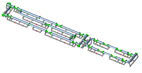
Multi-Mode Metering Skid with Undefined Connecting Piping
The unit assessed was a 24-inch, 300# ethane metering skid. Gas can be routed through a normal operating line (line 1), a testing and maintenance line (line 2), two flow control lines (lines 3 and 4) and a bypass. No more than one flow control line operates at a time. The routings give four normal operating modes (A to D) and two test modes (E and F), each with its own temperature distribution. In the test modes, lines 1 and 2 are active together with line 3 or line 4, with flow through the bypass.
The assessment covered the piping, structural steel, anchor bolts and lifting lugs during installation and operation, with wind and seismic loads applied. No information was available on the connecting piping at either end of the skid.
CAESAR II Model of the Skid Piping and HEB Support Steel
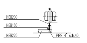
The piping and the proposed supporting steelwork were modelled together in a single CAESAR II model and analysed for quasi-static load conditions. Piping smaller than 4 inches was excluded. The frame used HEB profiles: HEB 200 for horizontal beams off the ground, HEB 180 for vertical beams and HEB 220 for horizontal beams on the ground, with 4-inch schedule 40 pipe as cross supports of the on-ground beams. Material properties for API 5L Gr. B piping and S355 structural steel (yield stress 355 MPa, ultimate tensile strength 470 MPa) were applied.
The positions of the 4-inch cross supports were optimised against the stress results, and one anchor point and two guide points were added to the support arrangement on the supplied drawing.
45 Load Cases for the ASME B31.3 Skid Assessment
The 45 load cases comprise 1 hydrotest, 7 operating, 7 sustained, 8 occasional and 22 expansion cases. The occasional cases combine weight, pressure and temperature for all pipes operational with either seismic loads (four cases) or wind loads (four cases). The 22 expansion cases are differences between pairs of load cases: seven from cold to an operating condition (modes A to F and all pipes operational) and fifteen between modes. Every case was applied to two temperature models, a cold day with empty pipe at 32 °F (0 °C) and a hot day with empty pipe at 160 °F (71 °C), both with flowing gas at 120 °F (49 °C), at a design pressure of 433 psig (29.85 barg). The largest temperature differences occur in the cold-day model, and the largest expansion stresses are expected there, so the results are reported for that model; the hot-day results were also checked.
ASME B31.3 paragraph 302.2.4 sets requirements for treating pressure and temperature variations as occasional. The code does not state when a temperature range is occasional, so the requirements were applied to temperature ranges as an interpretation. Of the fifteen mode-to-mode expansion cases, the thirteen other than normal operation (cases i and x) were treated as occasional, because the cases do not concern overpressures and their number of occurrences is below the stated limit of 1,000. Over the design life of 20 years, normal operation was assumed to occur 2,000 times in total, the cases where one flow measuring line replaces the other (ii, iii, vi and vii) 100 times and the testing cases 40 times. The stresses of the occasional cases were computed, reported and checked as not excessively large, but are not accounted for in the stress assessment. The variation from shutdown to each operating mode was considered separately.
Expansion stresses were assessed with a cyclic reduction factor f of 1.0 as an initial conservative value. The factor is allowed to be raised to 1.2 for low cyclic operation of up to 2,000 changes between modes A and B and between modes C and D in the design life. Seismic loads followed SAES-A-112 and ASCE/SEI 7-05, with a short period acceleration of 8.8%g, a factor F of 1.4, an importance factor of 1.25 and a dynamic load factor of 2. The resulting design acceleration is 0.062g. Wind loads followed SAES-A-112, with a basic wind speed of 40.3 m/s, a drag coefficient of 0.65 and four horizontal directions.
Pipe, Steel, Anchor Bolt and Lifting Lug Checks
All load cases conformed to ASME B31.3 with a cyclic reduction factor of 1.0 for all cases, and the flange connections were checked for excessive loads. In the structural steel (S355), the allowables are 157 MPa for sustained and occasional stress (the lower of two thirds of yield stress and one third of tensile strength) and 235 MPa for expansion stress (1.5 times the sustained allowable). The maximum stresses were 47 MPa for sustained and operational cases (30% of allowable), 68 MPa for occasional cases (43%) and 61 MPa for expansion cases (26%). Welds were not calculated; weld sizing must not limit the frame strength.
| Maximum stress [Mpa] | Maximum stress ratio [%] | |
| Sustained/Operational | 47 | 30 |
| Occasional | 68 | 43 |
| Expansion | 61 | 26 |
Maximum stresses in the structural steel by load case category, with ratios relative to allowables of 157 MPa (sustained and occasional) and 235 MPa (expansion).
The anchor bolts are ASTM A307 Gr. A, 7/8 inch, with allowables of 155 MPa in tension and 82.5 MPa in shear in line with SABP-Q-001, and the bolt loads were within these allowables. To cope with thermal expansion of the frame, additional bolt hole clearance was specified: Type I has 2 mm lateral and 0 mm longitudinal clearance, and Type II has 2 mm lateral and 5 mm longitudinal clearance. The 5 mm value is based on the largest separation between anchor bolts in a frame, 3,700 mm. It is not known whether the clearances already on the received drawings allow for thermal expansion; if they do not, the specified clearances must be added to them.
Type 2T lifting lugs were assigned to two frames, Type 4T to twelve frames and Type 6T to three frames. The types are expected to carry loads up to 20 kN, 40 kN and 60 kN respectively. Lug strength was checked against the vendor maximum lift loads, which are assumed to include a margin for dynamic effects during lifting. The calculation covers horizontal lifting only. The actual load on a lug is the vertical load divided by the cosine of the sling angle, and the sling angle shall not exceed 40 degrees from vertical. With this configuration, frame stresses do not exceed 52 MPa, which is 33% of the sustained allowable.
Nozzle Stiffness Data for Connecting Piping Analysis
With no information on the connecting piping, the nozzles at the inlet and outlet flanges were analysed completely free to determine maximum displacements and completely fixed to determine loads. Nozzle stiffness in the lateral and rotational directions was calculated from the displacements and the highest nozzle loads. The free-nozzle case is the analysis reported in the assessment, and the stress levels with fixed nozzles do not conform to ASME B31.3. The reported stiffness and displacements are for the party responsible for the connecting piping, who must ensure that the loads on the skid flanges are not too high.