
The station model of the Winksele Compressor Station, to be built in Belgium, was divided into two models with some mutual overlap, a compressor model and a filter model, each covered by a separate stress report. A third report covers the gas air coolers as model C, an add-on to the compressor report (model B). This case study covers model C, which assesses the final design of the cooler distributor and the cooler nozzles.
Layout and Operating Conditions of the Gas Air Cooler System
The station has four gas air cooler systems, identical apart from the underground sections of the 20″ lines that connect the coolers to the 30″ compressor lines. Gas enters the 20″ cooler inlet line after passing the compressor. A 20″ distributor manifold feeds it into the four header boxes on the inlet side of the cooler through eight 10″ nozzles. The cooled gas leaves the cooler in an identical manner and returns through the 30″ compressor suction line, upstream of the compressor.
The operating pressure P1 is 70 Barg or 84 Barg, the maximum operating temperature T1 is 45°C or 85°C, the minimum ambient temperature T2 is -20°C or 5°C and the hydrotest pressure is 125.84 Barg or 134 Barg. The different operating pressures and temperatures apply to the inlet and outlet of the cooler system. The system consists mainly of above ground piping, with some buried sections subject to long term soil settlement.
Model Scope, Boundaries, Soil Modelling and Load Cases
Only one of the four coolers is modelled in detail. Cooler E-1620208 was selected because it has the longest hot 20″ inlet line. Model B assesses the underground sections of the 20″ lines and the 20″ cooler connecting lines of all four cooler systems.
The static stress model was built and analysed in CAESAR II. It includes the 20″ cooler connecting lines, the cooler distributor, the cooler nozzles and the weight of the header boxes. Piping of 3″ and smaller is outside the scope and is not modelled or analysed. The pipe materials are API-5L B, X52 and X60, with allowable stresses at 70°C of 137.9 MPa, 151.7 MPa and 172.4 MPa respectively, based on one third of the tensile strength under ASME B31.3. A mineral wool insulation layer 100 mm thick is applied on all above ground piping. The above ground valve and silencer are vertically supported, with weights based on vendor data.
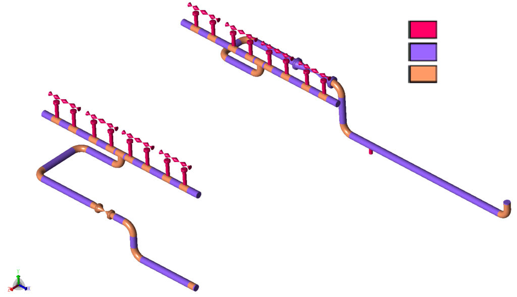
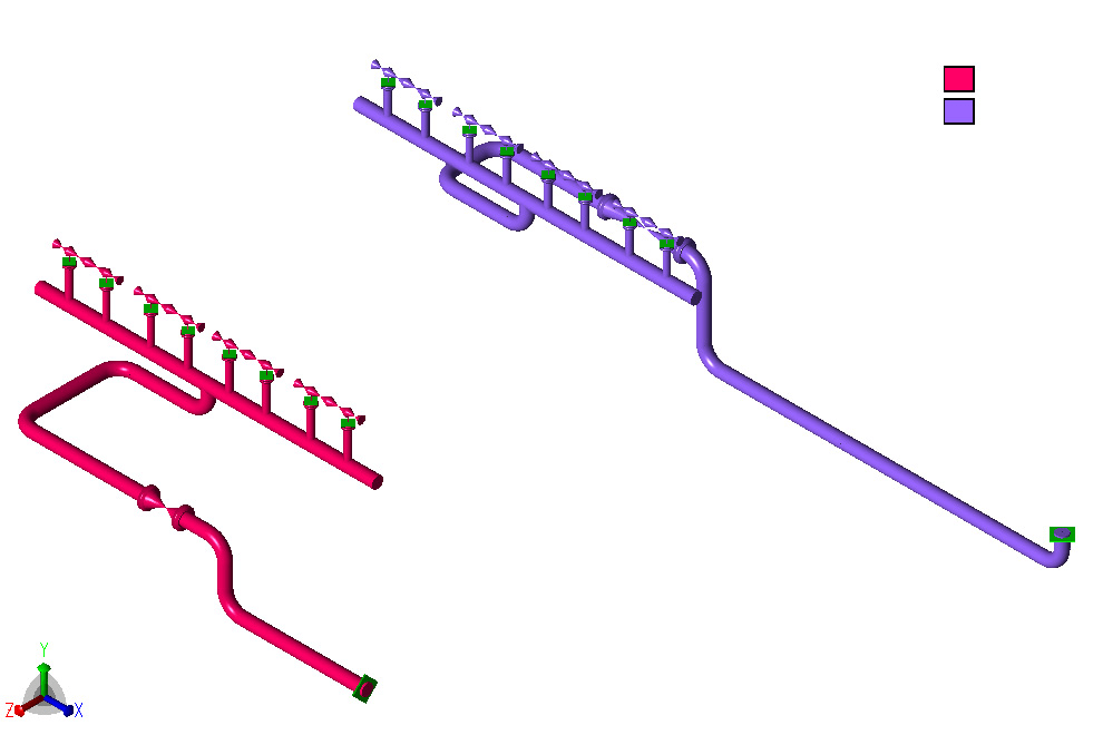
The model is cut off where the 20″ lines join the 30″ compressor suction and discharge lines, and anchors are introduced at these points. The relevant thermal and long term settlement displacements at these anchors are taken from model B and applied for the operating load cases. The cooler has four header boxes on each side, modelled as rigids. They are supported in the vertical direction only and are free to lift off, and the supports carry a weight of 1600 kg per header box. The inlet side header boxes are fixed in the N-S direction, the outlet side header boxes are free in the N-S direction and both sets are free in the E-W direction. The thermal expansion of the outlet side header boxes, 11.6 mm in the northern direction at an operating temperature of 85°C, is applied as a displacement. At the minimum ambient temperature of -20°C the cooler framework contracts, which brings the header box supports closer to the distributor supports by 0.67 mm on the outlet side and 0.61 mm on the inlet side.
Soil is represented by bilinear springs in the axial, horizontal and vertical directions, modelled to NEN3650-1 as in the compressor model. Two soil models are used for the buried 20″ piping: soil model 3 for a cover depth of 1225 mm and soil model 4 for 2500 mm. Long term settlement is applied as vertical displacements on the relevant vertical soil springs, with assumed values of 50 mm for non-compacted soil, 3 mm for the concrete slabs and 1 mm for the cooler base and everything attached to it. The longer inlet line is placed on four concrete slabs, mainly to reduce the reaction force on the support within the compressor building. The shorter outlet line has a single underground support, just before the bend after which it rises vertically to above ground level.
Thirty-two load cases are analysed: the hydrotest as an occasional case (case 1), the sustained case of weight and pressure (case 22), four operating cases at maximum operating temperature and minimum ambient temperature with and without soil settlement (cases 2 to 5), sixteen operating cases that add wind (cases 6 to 21), four occasional cases of weight, pressure and wind (cases 23 to 26) and six expansion cases (cases 27 to 32). The wind cases use a uniform wind velocity of 44.44 m/s, based on information from the stress report of the cooler vendor, applied in the +X, -X, +Z and -Z directions.
Piping Stress, Nozzle Load and Flange Results
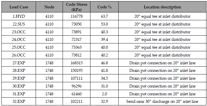
All stresses for the analysed load cases remain within the ASME B31.3 allowables, given the assumptions stated above. Of the hydrotest, sustained, occasional and expansion cases, the hydrotest case has the highest percentage of the allowable: 63.7 percent (116778 kPa) at node 4110, the 20″ equal tee at the inlet distributor. The sustained case reaches 53.0 percent (73050 kPa) at the same node. The four occasional wind cases reach 39.4 to 40.3 percent there, the highest being the +X wind case at 40.3 percent (73891 kPa). The highest expansion result is 46.8 percent (168315 kPa) in case 27, at the drain pot connection on the 20″ inlet line (node 1748).
The loads and moments at the 10″ cooler nozzles are checked against the 1 x API Standard 661 limit. The largest loads and moments occur in the operating load cases at maximum and minimum temperature, with and without long term settlement. Adding wind gives only a small increase. Wind in the northern (+Z) direction appears most significant at maximum operating temperature and wind in the western (+X) direction at minimum ambient temperature. All nozzle loads remain below the maximum allowed values. The largest load fractions occur for the vertical forces on the nozzles. Long term settlement has minimal influence on the nozzle loads.
All four flange connections in the cooler model are checked for equivalent pressure with the Koves factor included, following Stoomwezen D07071, section 4.3. The loads on the flanges remain below the allowable limits and the equivalent pressures remain below the pressure ratings.
Thermal Expansion and Support Arrangement of the Cooler Lines and Distributor
Cooler E-1620208 is the most critical of the four coolers, since its connecting line expands thermally in the direction of the cooler and is restrained by the 30″ compressor line in the other direction. The expansion loops in the above ground 20″ cooler connecting lines are each held with a single support, placed halfway along the N-S leg of the loop on the inlet side and on the more northern side of the N-S leg on the outlet side. The supporting layout of the 20″ cooler distributor is taken from the vendor proposal. In some cases Teflon sliding plates are required to reduce the friction coefficient to 0.1. The above ground valve and silencer on the 20″ cooler lines are slightly lifted from their supports by thermal expansion in the vertical section coming from underground level.
Frequently asked questions
Why is only one of four identical gas air coolers modelled in a pipe stress analysis?
The four coolers are identical apart from the underground sections of the 20″ lines, which model B assesses together with the 20″ connecting lines of all four coolers. Cooler E-1620208 was selected because it has the longest hot 20″ inlet line, which expands toward the cooler while the 30″ compressor line restrains it in the other direction.
Which load cases are analysed for a gas air cooler piping model?
32 load cases in CAESAR II: the hydrotest as an occasional case, one sustained case, four operating cases with and without soil settlement, sixteen operating cases that add wind, four occasional wind cases and six expansion cases. The wind velocity is 44.44 m/s, applied in the +X, -X, +Z and -Z directions.
How are gas air cooler nozzle loads checked against API Standard 661?
The loads and moments at the 10″ nozzles are checked against the 1 x API Standard 661 limit. The largest loads and moments occur in the operating load cases at maximum and minimum temperature, wind adds only a small increase, and all nozzle loads remain below the maximum allowed values.