
Dynaflow ran a finite element analysis to ASME VIII Division 2 of a stainless steel SA240 316L support ring welded into a carbon steel Claus reactor. All primary stresses were within the allowable. At the head-to-ring connection, however, secondary stress reached 885 MPa (259 percent of the allowable), and fatigue stress with the Ke factor applied was 134 percent of the allowable. The carbon steel partition plate between two sub-reactors met all primary, secondary and fatigue limits, with a maximum occasional pressure difference of approximately 1 Barg.
Stainless Steel Support Rings in a Carbon Steel Claus Reactor
The reactor has three sub-reactors, each with an internal support ring welded along the shell, head and partition plate. The ring carries the weight of the catalyst grid and counterbalances the pressure drop across the grid. The client indicated that these rings are normally made from carbon steel (15Mo3). In this reactor they are made from stainless steel SA240 316L and welded to carbon steel SA516 Gr.60 shells, heads and partition plates.
The calculation metal temperatures are 300°C for the stainless steel ring and 220°C for the carbon steel shell and head. The expansion coefficient is 17.6×10⁻⁶ mm/mm/°C for SA240 316L and 12.5×10⁻⁶ mm/mm/°C for SA516 Gr.60. The temperature difference and the different expansion coefficients produce differential thermal expansion, and high stresses were expected at the intersection of the ring and the reactor wall. The head sections are vulnerable because the possibility exists that the ring will cause plastic deformation in the head.
Reactor 3 was identified as the most critical location for the ring and was used as the basis for the support ring calculations. Its ring is located closer to the centreline of the shell and is welded to a semi-elliptical head. The client specified a minimum of 50 pressure plus thermal cycles from start-up and shutdown.
FE-Pipe Models of the Support Ring and Partition Plate
Two details were modelled with the finite element solver FE-Pipe and checked against ASME VIII Division 2. Model A is the stainless steel ring, analysed for reactor 3 at a calculation pressure of 4.3 Barg.
Model B is the carbon steel partition plate between reactors 1 and 2, which the client identified as the most critical partition plate. Its thickness is 20 mm uncorroded and 17 mm corroded. Reactor 1 was assumed to be operating and reactor 2 offline. The calculation metal temperatures are 300°C, 160°C and 20°C, and the calculation pressure difference across the plate is 0.33 Barg. The thermal gradients and the pressure difference subject the plate to bending stresses, and the highest stresses were expected in the fillet weld that attaches the plate to the shell. The same minimum of 50 pressure plus thermal cycles applies.
The standard FE-Pipe templates do not support a ring offset from the vessel centreline, so the geometry of Model A was modelled and meshed in AutoCAD. Because the thicknesses are relatively small, Model A is built from shell elements. The model is truncated at the partition plate, so the ring plate welded to the partition plate is not modelled, and stresses near the truncation are less reliable. The most critically stressed components were expected to be the head and shell, not the partition plate, and the stresses in the ring plates welded to the partition plate are of a similar level to those in the ring along the shell.
Two of the three stiffener ribs attached to the head were omitted to simplify the mesh. Because the stresses are due to thermal expansion, the influence of these ribs on that stress condition is relatively small.
The mesh was refined near the ring weld to capture the secondary stresses. These typically attenuate with √(Rt) from the weld, where R is half the reactor diameter and t is the shell or head thickness. Fixity (3 degrees of freedom) and anchor (6 degrees of freedom) restraints were both applied, and the stresses away from the truncation varied little.
The minimum wall thicknesses used were 9 mm for the semi-elliptical head, 12 mm for the shell and 11 mm for the stainless steel rings. The head thickness is the minimum thickness after forming given in the drawings.
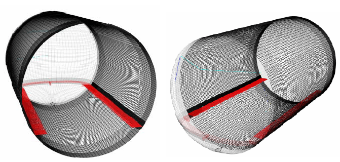
Three load cases were checked: sustained, operating and expansion (FE-Pipe load cases 2, 4 and 5).
In the sustained case, local primary membrane plus bending stress (PL+PB) is compared with 1.5Smh, where Smh is the hot allowable stress. In the operating and expansion cases, PL+PB+Q is compared with 3Sm,avg, three times the average of the hot and cold allowable stresses. PL+PB+Q contains both primary and secondary stress; it is referred to as secondary stress because the check is against ratcheting. The expansion case also carries a fatigue assessment of the peak stress (PL+PB+Q+F).
The cold and hot allowable stresses are 115 and 71 MPa for SA240 316L and 118 and 109 MPa for SA516 Gr.60, with the hot values at 340°C. For SA240 316L, the more conservative of two hot values defined in ASME Section II is used.
Where PL+PB+Q exceeds 3Sm,avg, ASME VIII Division 2 section 4-136.7 permits the thermal bending stress (Qt) to be subtracted and the result compared with 3Sm,avg again. The fatigue stress is then multiplied by a strain factor Ke to account for a reduced fatigue allowable. All stresses reported are stress intensities, defined as twice the maximum shear stress.
Model B was built as an axisymmetric brick model to capture through-wall stresses and temperatures. A brick model was required because of the high temperature gradients, the relatively large wall thicknesses, and the insulation and refractory. A thermal run gave the temperature distribution before the secondary stress analysis. The stress calculations used the corroded condition.
Sharp weld toes in a linear elastic brick model produce stress singularities, and the peak stress grows without bound as the mesh is refined. To judge the stress at the weld toe, the expansion stress further from the weld was linearly extrapolated to the toe, an approach described in AD-Markblatter Section S2. The linearised stress was compared with a fatigue curve.
ASME VIII Division 2 Results for the Ring and Partition Plate
In Model A, the primary stresses (PL+PB) in the sustained load case were within the allowable. The three highest were:
- 61 MPa (38 percent of the allowable) in the head
- 55 MPa (34 percent) at the head knuckle
- 46 MPa (43 percent) in the ring plates
The secondary stresses (PL+PB+Q) from the operating and expansion load cases exceeded 3Sm,avg. The ring plate stress was mostly membrane stress.
| Location | PL+PB+Q (MPa) | Percent of 3Sm,avg | After Qt subtraction | Fatigue (Ke applied) |
|---|---|---|---|---|
| Head-to-ring connection | 885 | 259 | 142 percent | 134 percent of the allowable |
| Ring plates | 596 | 213 | 180 percent | Acceptable for 50 cycles |
| Head rib (modelled) | 368 | 131 | Just within allowable | Not reported |
| Shell ribs | Not reported | 107 | Just within allowable | Not reported |
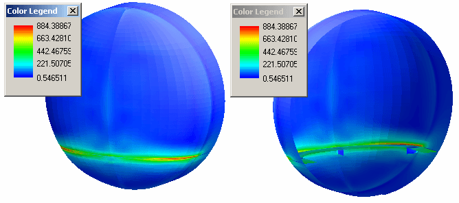
The head-to-ring connection stayed above the allowable after the thermal bending subtraction, and its fatigue stress exceeded the allowable even for 50 cycles. The ring plates also stayed above the allowable after subtraction, although their fatigue stress was acceptable for the 50 pressure plus thermal cycles. The high stresses in the head are of concern because the head is a pressure containing part of the reactor.
In Model B, all stress categories (primary, secondary and fatigue) were within the allowable. In the sustained load case, the highest weld toe stress was 128 MPa at the mesh density used, which is within the allowable; this stress increases as the mesh is refined. The highest expansion stress at a weld toe was in reactor 2 (top weld). Its linearised stress had a maximum of approximately 125 MPa, and the allowed number of cycles was larger than the 50 specified. The maximum relative axial displacement at the plate centre, from thermal and pressure bending, was approximately 6 mm for the corroded plate and 4 mm for the uncorroded plate.
The maximum occasional pressure difference was assessed for the corroded plate. An explosion was treated as an occasional primary load, so only primary stresses apply. The local primary stress was checked against 1.5kSmh, with k = 1.3, which gives an allowable of approximately 210 MPa in the model. In a series of FE simulations, the pressure across the plate was varied and the weld toe peak stresses were ignored. The highest occasional load that can be applied to the plate is approximately 1 Barg.
Differential Expansion Findings and Ring Modification Options
In Model A, the primary stresses were within the allowable and the secondary stresses were not. Differential thermal expansion between the ring and the outer shell generates the excessive secondary stresses in the ring plates and the excessive secondary and fatigue stresses in the head. In the head, the ring is pressed into the head section by its thermal expansion. This causes high local bending and membrane stresses in the head and plate structure.
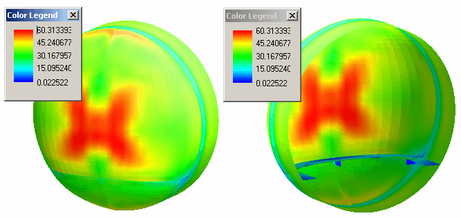
Three options to reduce the stresses are listed, starting with the most effective but least practical.
- Replace the stainless steel ring with a carbon steel equivalent.
- Detach the ring at the head; the head part of the ring should then be supported by welded ribs. Cuts (slots) can be added to reduce the membrane stresses in the ring plates welded to the cylindrical part. If these slots are ineffective, the ring weld should be removed completely and the ring supported by ribs only.
- Add two cuts (slots) in the ring plate on each side of the shell and head transition, as suggested by the client. This will help to reduce the stresses in the head and ring plates, but it is not certain that all stresses would fall below the allowable bending stresses in the head are still expected to be quite large, and membrane stresses in the ring plate along the shell are still expected to be too large. Additional cuts in the ring along the shell could help.
Frequently Asked Questions
Why does a welded stainless steel support ring cause high stress in a carbon steel reactor head?
In this reactor, the SA240 316L ring has a calculation metal temperature of 300°C and the SA516 Gr.60 shell and head have 220°C. The ring’s expansion coefficient is 17.6×10⁻⁶ mm/mm/°C against 12.5×10⁻⁶ mm/mm/°C for the carbon steel. Thermal expansion presses the ring into the head, which causes high local bending and membrane stresses. The finite element analysis found secondary stress (PL+PB+Q) of 885 MPa at the head-to-ring connection, 259 percent of the 3Sm,avg allowable, while all primary stresses were within the allowable.
What does ASME VIII Division 2 permit when PL+PB+Q exceeds 3Sm,avg?
Section 4-136.7 permits the thermal bending stress (Qt) to be subtracted and the remainder rechecked against 3Sm,avg. The fatigue stress is then multiplied by a strain factor Ke to account for a reduced fatigue allowable. For this support ring, the head-to-ring connection stayed at 142 percent of the allowable after subtraction, and its fatigue stress with Ke applied was 134 percent of the allowable, even for 50 cycles.
How was the weld toe stress singularity in the partition plate model handled?
Sharp weld toes in a linear elastic brick model give peak stresses that grow without bound as the mesh is refined. The expansion stress further from the weld was linearly extrapolated to the toe, an approach described in AD-Markblatter Section S2, and the linearised stress was compared with a fatigue curve. The maximum linearised stress was approximately 125 MPa, and the allowed number of cycles exceeded the 50 specified.
What occasional pressure difference can the partition plate take?
Approximately 1 Barg, for the plate in corroded condition (17 mm). An explosion was treated as an occasional primary load. The local primary stress was checked against 1.5kSmh with k = 1.3, approximately 210 MPa in the model, with weld toe peak stresses ignored.
Which modifications were identified to reduce the ring stresses?
Three options were identified, starting with the most effective but least practical. The first is to replace the stainless steel ring with a carbon steel equivalent. The second is to detach the ring at the head and support that part on welded ribs, with optional slots in the ring plates along the shell. The third, suggested by the client, is two slots in the ring plate on each side of the shell and head transition. For the third option, it is not certain that all stresses would fall below the allowable, and all these solutions should be studied more closely.