
Slug Flow Operation and Two Elbow Fatigue Failures
At a gas-to-liquids facility, the water feed line to an HCN/NH3 stripper (1C-1201) regularly operated in the slug flow regime. Slugs can generate large dynamic loads on the piping, which can eventually result in fatigue failures. Two leakage incidents occurred, each caused by mechanical fatigue failure in an elbow and both identified as the result of the periodic impact of slugs.
The first incident was addressed by replacing the cracked bend and changing the supporting near it. The second cracked elbow, Bend9, was repaired temporarily with a clamp over the leaking elbow. The client requested a dynamic analysis of the piping and its supporting to provide a more rigorous solution to the slug impact.
CAESAR II Model, Material Inputs and Analysed Cases
The analysis used a CAESAR II model that includes the routing and supporting of the feed line, the heat exchanger (1E-1202A) and the stripper (1C-1201) to which the line connects. In several locations, the essential parts of the supporting structures were modelled to give more realistic support flexibility. The supporting arrangement is based on the situation after the first crack incident was solved and includes a strut from the column to the feed line that acts as an axial stop.
All 10 inch piping was modelled as A312 TP321 and the fitting material (A403 WP321) was not applied. This is conservative because the allowable for A312 TP321 is lower, while the stiffness properties are the same. A friction factor of 0.3 was applied to all rest supports and a mill tolerance of 12.5 percent was included.
Three cases were analysed, each with static and dynamic analysis. Case 1 is the as-is supporting without the clamp, which represents the system before the clamp was applied. Case 2 is the advised supporting with the clamp, modelled as an added mass of 220 kg distributed over the nodes of Bend9, with no added stiffness because the clamp is not an integral part of the piping and is connected to the bend through a gasket. Case 3 is the advised supporting without the clamp, which represents the system with the cracked bend replaced and the clamp removed.
Slug Force, Dynamic Analysis Methods and Fatigue Criterion
The slug force on an elbow was applied as a time-dependent load. The peak force is the product of the slug density, the pipe cross-sectional area and the square of the slug velocity. The rise time is the developed length of the bend divided by the slug velocity, and the duration is the slug length minus the developed length of the bend, divided by the slug velocity. The force was applied to each bend in turn as the slug flows downstream, starting at the third bend downstream of the heat exchanger, where slug flow was assumed to be developed.
The time-history analysis used forward time integration over 15 seconds, in which five consecutive slugs pass through the piping, and gave the stress amplitudes for evaluation. The spectrum analysis identifies the contribution of each mode shape to the total response, including the eigenmode that contributes most. It loses the time difference between slug impacts on consecutive elbows, so its results represent simultaneously acting forces on the included bends, which in general gives conservative stress results. Load case D4 applies the slug force to Bend5 to Bend10 and load case D5 applies it to Bend11 and Bend12.
The stress amplitudes were evaluated against the ASME VIII-2 fatigue curve for stainless steel, which has an endurance limit of around 80 MPa. For fittings a factor of 2 is applied to the stress amplitude, so amplitudes above 40 MPa in fittings can result in mechanical fatigue. Because of the limited accuracy of the beam model, all amplitudes above 25 MPa were discussed as a conservative measure.
Case 1 Static Stresses, Stress Amplitudes and Eigenmodes
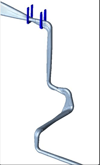
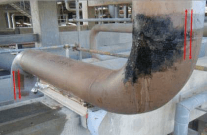
Eigenmode at 7 Hz that contributes most to the stress amplitude at Bend9, shown for a section of the piping with the as-is supporting (Case 1). Arrows mark the direction of motion.
In Case 1, the maximum static stresses are within the allowable: 40 percent of the allowable for the sustained case (S3), 41 percent for the wind cases (S4 to S7), 65 percent for expansion case S16 and 6.1 percent for expansion case S17.
The time-history analysis of Case 1 gave amplitudes above 25 MPa at three bends: Bend9, the location of the second crack incident (25.9 MPa), Bend11 (47.0 MPa) and Bend12 (29.4 MPa). Fatigue can be an issue at these three bends. Only Bend11 exceeds the 40 MPa value for fittings. Although Bend9 cracked, its amplitude is lower than half the endurance limit, most likely because of the limited accuracy of the model. An alternative explanation is that the stress intensification factor imposed by B31.3 is in some cases lower than results from finite element studies.
In load case D4, the eigenmode that contributes most to the amplitude at Bend9 has an eigenfrequency of 7 Hz and is consistent with the observed vibrations of the piping. In load case D5, the eigenmode that contributes most at Bend11 and Bend12 has an eigenfrequency of 2 Hz and is consistent with the observed up/down and East/West vibrations of the piping near the strut supports.
Advised Support Changes at Nodes 180, 220, 234 and 120
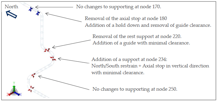
Cases 2 and 3 include the advised support changes, which eliminate some of the eigenmodes, in particular those with the largest contribution to the stress amplitudes. At node 180, the axial stop is removed because under thermal expansion it works against the axial function of the strut supporting near the stripper, the guide is given minimal clearance and the rest support is changed to a double-acting vertical restraint with minimal clearance. At node 220, the rest support is removed, a guide with minimal clearance is added and the axial stop is given minimal clearance. At node 234, around halfway along the vertical piping section near Bend9, a new support is added with a North/South restraint and an axial stop in the vertical direction, both with minimal clearance.
To reduce the amplitudes at Bend11 and Bend12, the gaps in the support at node 120 are closed, so that horizontal movements of the piping near the struts are less likely to result in lateral movements of the vertical piping next to the stripper column. All of these changes are essential to reduce the stress response to acceptable levels. They were checked for acceptability from a static (flexibility) point of view.
Stress Amplitudes and Static Stresses After the Support Changes
With the advised supporting the amplitudes are the same in Case 2 and Case 3: Bend9 1.1 MPa, Bend10 9.0 MPa and Bend11 13.2 MPa, with a model maximum of 13.8 MPa. In Case 1, Bend9 and Bend11 were 25.9 MPa and 47.0 MPa respectively. The model maximum of 13.8 MPa is below half the endurance limit, and no new location has an amplitude above 25 MPa.
The largest stress for wind cases S4 to S7 is 53.0 MPa in Case 2 and Case 3. Adding the maximum amplitude of 13.8 MPa gives (53.0 MPa + 13.8 MPa) / (115 MPa × 1.33) = 44 percent of the applicable allowable. The maximum static stresses are within the allowable: for Case 2 and Case 3 respectively, 38 and 39 percent of the allowable for S3, 34.6 and 35 percent for S4 to S7, 66 and 65 percent for S16, and 7 percent for S17 in both.
Restraint Gaps and Trunnion Supports in Slug Flow Piping
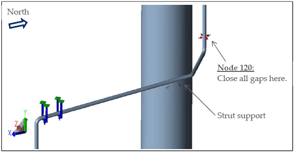
Some gaps in the lateral restraints of the vertical piping next to the stripper are 30 mm in size, practically removing the function of those restraints. Closing the gaps at node 120 is essential and reduces the stress response at Bend10. Reducing the gap size of all lateral restraints of this vertical section is also advised.
The remaining trunnion supports can be replaced by supports on the feed line just upstream or downstream of the elbows, which removes the stress concentration at the trunnion. The modification is wanted because a similar trunnion support led to fatigue cracking in the first incident. At node 311, where a trunnion support is replaced, the 3 mm North/South clearance is kept to accommodate thermal expansion. The additional gap reductions and the trunnion replacement are not essential to reduce the amplitudes below the endurance limit.
Frequently Asked Questions
What causes fatigue cracking in piping elbows exposed to slug flow?
Both leakage incidents were mechanical fatigue failures in an elbow and were identified as the result of the periodic impact of slugs.
What stress amplitude limit applies to stainless steel fittings in a slug vibration analysis?
The endurance limit is around 80 MPa and a factor of 2 applies to fittings, so amplitudes above 40 MPa can result in mechanical fatigue.
How can support changes reduce slug-induced stress in a piping system?
The changes eliminate some of the eigenmodes, and the model maximum stress amplitude is 13.8 MPa afterwards.