
Compressor Piping Under Combined Marine and Process Loading
The compressor module was located roughly halfway along the hull. Its connected piping had to accommodate thermal and pressure loads, wind loads, accelerations from wave-driven barge rocking and relative displacements from hull deformation. These loads could produce pipe deflection and bending and increase compressor nozzle loads.
The assessed lines were a 54 inch low-pressure suction line, a 36 inch medium-pressure suction line, a 28 inch high-pressure side-stream suction line and a 28 inch discharge line. Suction design conditions were 20 barg and -70 to +40°C. Discharge design conditions were 40 barg and -70 to +180°C.
The analysis used wind speeds up to 36 m/s during operation and 75 m/s along the barge centreline during survival conditions, with the compressor shut down. Lateral wind components were neglected. Operating accelerations were 0.04 g vertically, 0.04 g transversely and 0.02 g longitudinally. Survival accelerations were 0.13 g vertically, 0.26 g transversely and 0.15 g longitudinally.
API 617 Nozzle Limits and Piping Flexibility
Compressor nozzle loads were the main constraint for this large-bore piping. API 617 Appendix G provided a combined limit on resultant force and moment, using an equivalent nozzle diameter for connections larger than 200 mm.
These allowable loads corresponded to bending stresses below 10 MPa in the connected pipe. For the 54 inch suction line, the corresponding bending stress limit was 2.0 MPa. Even with a factor of 1.6, the corresponding limit was 3.2 MPa, compared with the material allowable stress of 137.9 MPa.
Accommodating wind and barge motion called for a restraining support arrangement, while reducing loads from thermal expansion called for maximum flexibility. The feasibility assessment examined whether the proposed piping and support arrangement could accommodate both requirements within the nozzle load targets.
Modelling and Support Strategy in CAESAR II
Wall thickness selection was based on pressure containment at design pressure in A312 Type 316 stainless steel. The material allowable stresses were 137.9 MPa at 40°C and 133.6 MPa at 180°C. Thicknesses used in the analysis were 11.30 mm for the 54 inch suction line, 7.92 mm for the 36 inch suction line, 6.35 mm for the 28 inch suction line and 12.70 mm for the 28 inch discharge line.
Each line was modelled individually in CAESAR II using marked-up isometrics. The piping was kept as short as possible to limit exposure to wind and inertia loads from ship movement, while retaining sufficient flexibility to limit bending loads at the compressor nozzles. Expansion loop rotation near the compressor was selected so that forces and moments partly cancelled in the combined load assessment. Support arrangements were refined iteratively to minimise nozzle loads.
All suction lines were supported at the same level, with the discharge line supported at a slightly higher elevation. Supports near the compressor were spring supports.
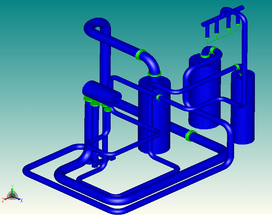
In-plane deck deformation was assumed absent. The predicted longitudinal deformation was sinusoidal, with a half wavelength equal to the 470 m barge length and an amplitude of about 350 mm. Differential deflection was negligible at the mid-barge module location. The predicted lateral differential displacement was 0.1 to 0.2 mm per metre. The springs were expected to accommodate this gradient with negligible effect on nozzle loads.
Operating and Survival Nozzle Load Targets
Targets were three times NEMA allowable loads for operating conditions and five times NEMA for survival conditions. API 617 allowable loads were equivalent to 1.85 times NEMA, giving project targets of 1.62 times API 617 for operation and 2.7 times API 617 for survival.
These targets were based on allowable load information from potential compressor suppliers. The limits appeared acceptable to those suppliers.
Condition | NEMA multiplier | API 617 multiplier |
Operating | 3 | 1.62 |
Survival | 5 | 2.7 |
Line-by-Line Nozzle Loads and Pipe Stresses
The 36 inch medium-pressure suction line and the 28 inch high-pressure side-stream suction line met the targets across design, normal operation, upset and survival conditions with the proposed routing. An ALT 1 routing for the 28 inch suction line could further improve the combined assessment if a reduction was required.
For the 54 inch suction line, design and normal operating results were within target. Exceedances occurred in some upset combinations involving hot operation, ship movement and wind, and in survival conditions. The line was considered acceptable with the recommended ALT 1 routing. Changes in line elevations were proposed to avoid clashes associated with that routing.
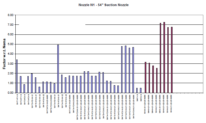
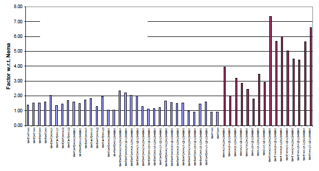
The 28 inch discharge line remained within the operating target under design and normal operating conditions. Some survival combinations exceeded five times NEMA. An ALT 1 routing was proposed to improve these results.
The combined API 617 assessment showed peaks in Mz moments. Implementing the ALT 1 routings for the 54 inch suction, 28 inch suction and 28 inch discharge lines could improve individual results and reduce the combined peaks. Acceptable results were considered feasible.
Material stresses were assessed against ASME B31.3 and were acceptable for all assessed layouts and load cases.
Combined Nozzle Loads and Routing Changes
The combined assessment remained relevant where individual lines met their nozzle load targets. The optional ALT 1 change to the 28 inch side-stream suction line was proposed to assist the combined assessment if required. Small routing changes could improve the remaining nozzle load exceedances.
Frequently Asked Questions
What nozzle load targets were used for the FLNG compressor piping?
The project targets were three times NEMA allowable loads for operating conditions and five times NEMA for survival conditions. These corresponded to 1.62 and 2.7 times API 617 respectively.
Which compressor suction lines met the nozzle load targets with the proposed routing?
The 36 inch medium-pressure suction line and the 28 inch high-pressure side-stream suction line met the targets across design, normal operation, upset and survival conditions with the proposed routing.
Did the compressor piping meet ASME B31.3 stress limits?
Material stresses were acceptable for all assessed layouts and load cases when assessed against ASME B31.3.