Operating Context and Damper Configuration Assumed
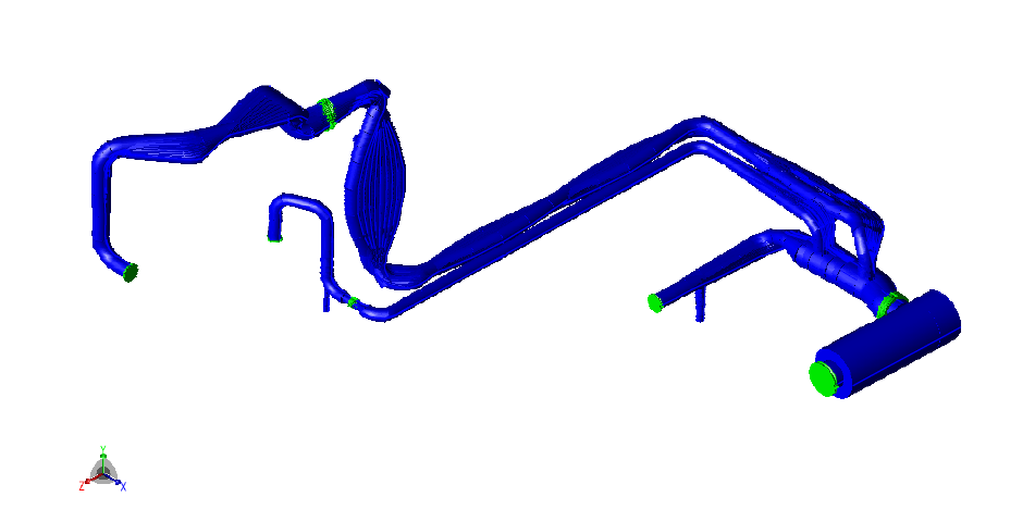
At a plant in Qatar, a Dresser Roots compressor compresses seal gas in two stages. The client requested a simulation study, both acoustic and mechanical, of the compressor piping between the first-stage discharge and the second-stage suction. The second-stage bypass lines are included. The basic compressor frequency is 49.3 Hz.
The discharge damper was modelled without its internals, based on information received from the client. The study determined the acoustic and mechanical natural frequencies, verified the possible occurrence of vibration resonance in the downstream piping, and verified the pressure oscillations and the unbalanced loads (shaking forces).
Three-Stage Analysis with Parallel Manual Calculations
The analysis had three stages. First, the acoustic and mechanical natural frequencies were determined. Second, the mechanical natural frequencies, calculated in CAESAR II, were used to verify the possible occurrence of vibration resonance in the downstream piping. Third, an acoustic simulation verified the pressure oscillations and the shaking forces.
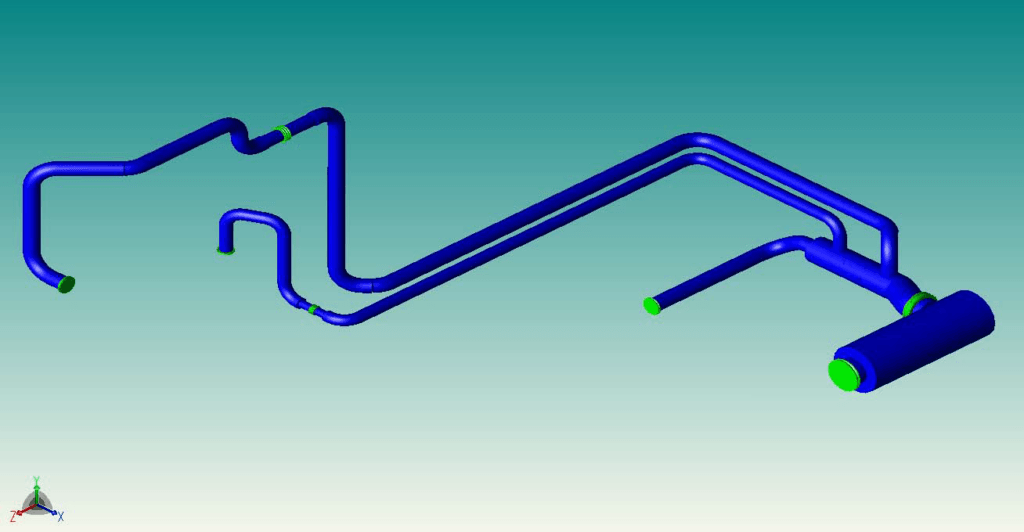
The acoustic simulation imposed a fixed-pressure boundary condition at the downstream ends of both the discharge piping and the second-stage bypass piping. At the upstream end, the first-stage discharge nozzle, an average volume flow of 4.59 m³/s was specified, with a superimposed harmonic component of 1.67 m³/s amplitude at 49.3 Hz. The amplitude was based on the 3545 cfm supplied by the client. The acoustic natural frequencies were determined by exciting the system with a flow step function at the discharge nozzle and applying a Fourier transform to the pressure response at different nodal locations. The shaking forces from the simulation were used in a response analysis of the piping system.
In parallel, two manual calculations estimated the pressure oscillation at the first-stage discharge nozzle in the absence of wave reflection effects. They were based on the participation of the nozzle volume in the windkessel effect of the compressor plenum. The nozzle length is 12% of the acoustic wavelength, so retardation effects in the nozzle at the basic compressor frequency of 49.3 Hz were assumed to be small. The first calculation used the 3545 cfm flow information. The second used a flow oscillation with an amplitude of 4.59 m³/s, assuming completely start-stop flow.
Acoustic Frequencies, Pulsation Levels and Stress Amplitude
The system showed a limited number of acoustic frequencies around the basic compressor frequency, so acoustic resonance was not expected. A number of low-frequency components were related to reflections between the bypass lines. The labelled peaks in the Fourier transform of the pressure response to the flow step were at 2.01, 4.3, 10.95 and 38.65 Hz in the manifold downstream of the damper, and at 2.01, 4.3, 6.25, 8.25, 11.1, 29.9, 38.65 and 44.6 Hz in the damper.
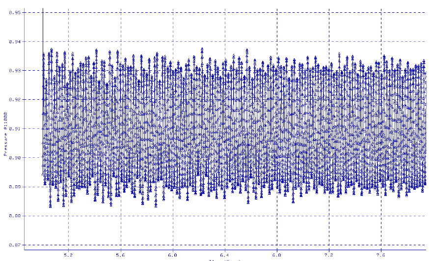
For the 3545 cfm flow, the manual calculation predicted a pressure oscillation at the discharge nozzle of 0.854 psi peak-peak. For completely start-stop flow, it predicted 2.2 psi peak-peak. For the same 3545 cfm flow, the acoustic simulation gave 0.812 psi peak-peak at the compressor discharge flange, which was 5% different from the manually calculated 0.854 psi. The simulation plot of the pressure at the compressor discharge nozzle shows 0.056 Barg peak-peak.
The maximum pressure oscillations occurred at the compressor discharge nozzle. In the damper without internals, the oscillations were at 55% of the discharge flange level, which was expected for a damper of this size. Downstream of the damper, the pulsations were reduced further to 20% of the compressor nozzle level. The simulation plot for the manifold downstream of the damper shows 0.01 Barg peak-peak. The pulsation levels in the discharge piping were at the 0.01 Barg level, below 1% of the average line pressure and hence acceptable.
The simulation with the 3545 cfm flow oscillation gave a shaking force at the manifold of 5.6 kN peak-peak. The response analysis of the piping system gave a maximum displacement below 0.1 mm and a maximum cyclic stress amplitude of 13 MPa, which was well below the endurance limit.
Modes Near 50 Hz and Acceptance for the Damper Without Internals
The mechanical natural frequency analysis gave 44 modes up to 100.100 Hz. The appendix shows mode shape plots for modes 24 to 29, from 40.8718 Hz to 50.1547 Hz. A few modes have frequencies around 50 Hz, and all are related to a bending mode of the manifold downstream of the compressor. This bending mode is not easily excited, and bending of the manifold can be eliminated relatively easily by improved supporting.
The simulation demonstrates that both pressure pulsations and cyclic stress levels are acceptable for the discharge piping with the damper internals removed. The latest information seems to indicate that the internals have not been removed, but this information arrived too late for the present analysis.