
CAESAR II stress analysis of 13 critical sections of a buried GRP fire water system, to ISO 14692, expected no problems for the underground piping under pressure and temperature loads. High stresses occurred in vertical above-ground GRP pipes where the pipe is vertically restrained; in section D, guide and rest supports in place of the U-bolts gave 83% (sustained), 68% (operating) and 94% (hydrotest) of the long-term allowable stress.
GRP Fire Water Pipe Failures and Critical Section Selection
A fire water system made from glass-reinforced polyester (GRP) pipe, mostly buried, had been in service for a couple of years when several pipe failures occurred in its early life. A pipe stress review was carried out to assess the stress condition of the system and the risk of future failures.
In the selected sections, the larger part of the piping has non-tensile resistant coupling joints, which allow some relative movement of the connected pipes, and the remainder has tensile-resistant joints. The joint type was concluded from the received drawings and the presence of thrust blocks. Concrete thrust blocks take the pressure thrust.
A stress analysis of the complete system was not carried out. Thirteen critical sections, labelled A to M, were selected before the project began, using experience with fibreglass piping systems and information about the failures that had occurred. The layouts of the selected sections in part resemble the layouts of the piping where failures occurred. The conclusions also apply to other sections with a comparable layout.
Modelling Buried GRP Pipe in CAESAR II to ISO 14692
Each critical section was modelled in CAESAR II, with the buried pipe modeller representing the soil resistance on the buried parts. The soil was sand, represented with the Peng soil model, and fittings cast in concrete were modelled as rigid elements. The analysis followed ISO 14692, which supplied the stress intensification factors for tees and elbows and the safety factors.
The design pressure was 16 barg, the hydrotest pressure 24 barg, and the design temperature 55 °C underground and 85 °C above ground. The general load cases were sustained (weight plus design pressure), operating (weight, design pressure and design temperature), operating with settlement, and hydrotest (weight plus hydrotest pressure). Each section was analysed for the interaction of pressure, thermal expansion, settlement and flexibility, and thrust block sizing was evaluated in sections E, H and J. Pressure peaks from fast valve closure, observed during an earlier site visit, were assumed to stay within the design pressure. The results are valid as long as the peaks do not exceed that level.
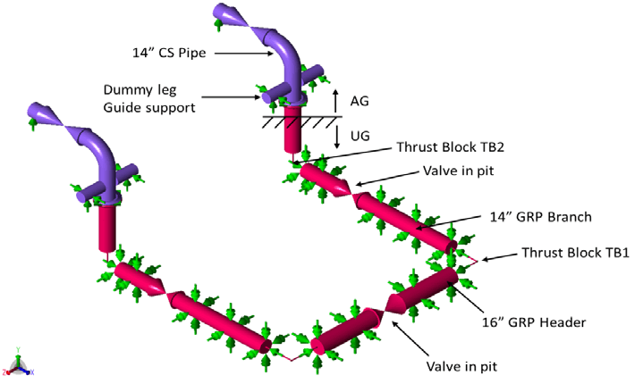
The model below shows section D: two 14-inch GRP branches from a 16-inch GRP header, each passing through a valve pit and rising through an elbow cast in a thrust block (TB2) to 14-inch carbon steel pipe above ground. A tee cast in a thrust block (TB1) joins each branch to the header.
Completing Pipe Data and Applying Settlement and Soil Variations
The manufacturer’s data were incomplete: long-term material properties and reinforced wall thicknesses were not available for all pipes. They were completed from Dynaflow experience with other fire water systems built with pipe from the same manufacturer, and only the reinforced wall thickness was used for strength. Thicknesses for 100 to 250 mm pipe came from reference projects. No usable values were found for 300 to 400 mm pipe, so the thickness-to-diameter ratio of the smaller pipes was applied at the lowest maximum allowable pressure computed for them (25 barg), using the long-term allowable hoop stress with a safety factor of 1.5. Assumptions were also made about the location and number of coupling joints.
The quantitative results therefore contain an uncertainty margin, and the qualitative findings are reliable. Some assumptions are essential to the results and should be verified in the field. If desired, verifying them with the pipe supplier can improve the quantitative accuracy.
Settlement was applied as a prescribed downward displacement of 0, 1, 3 and 5 mm at thrust blocks, representing well-compacted soil and excavation below the thrust block during construction, and of at most 3 mm at valve pits. In several analyses, an overburden compaction multiplier of 6 instead of 8 gave lower soil stiffness and lower bearing capacity, and a yield displacement factor of 0.005 instead of 0.015 gave higher soil stiffness.
GRP Riser Stress and Thrust Block Settlement Results
With only pressure and temperature loads, no problems are expected for the underground GRP piping, and where coupling joints are used they accommodate the expansion of the GRP piping. High stresses occurred at a few locations in the above-ground GRP piping, in vertical GRP pipes leading to and above the surface where the pipe is vertically restrained.
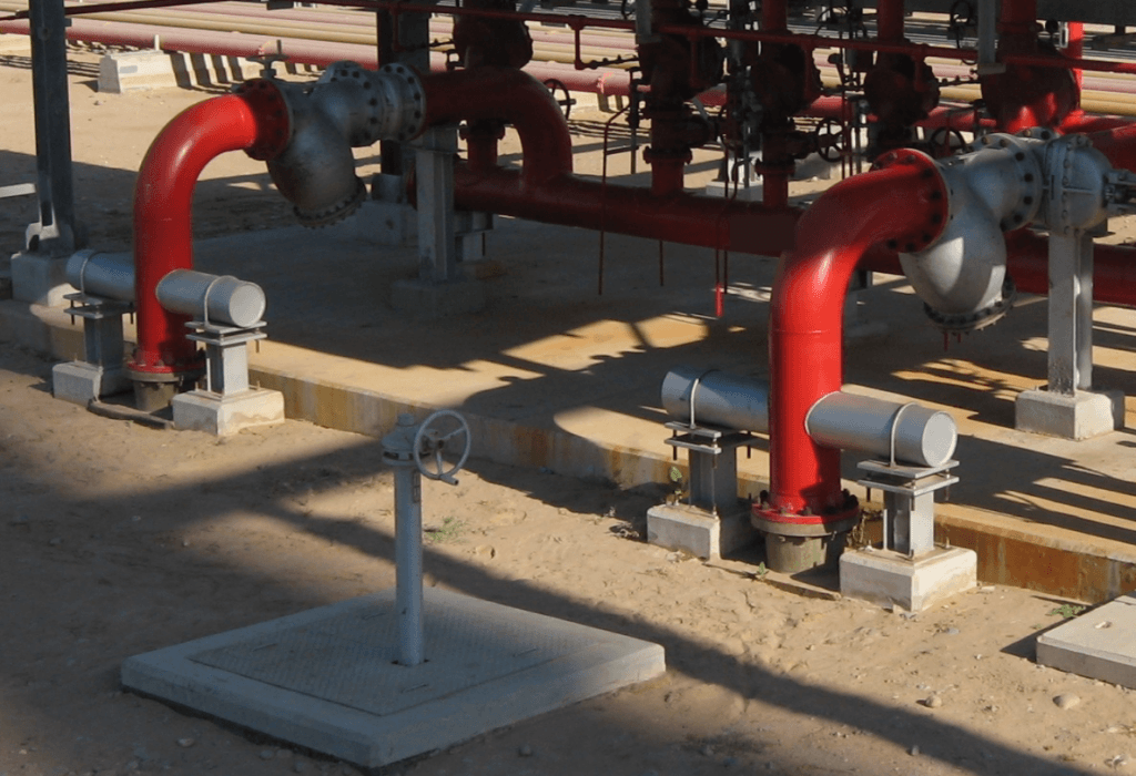
In section D, the information received indicated that U-bolts fixed the dummy-leg supports of the carbon steel pipe to their base plates. This restraint prevents upward expansion of the GRP riser, and the analysis gave an overstressed GRP pipe. With guide and rest supports in place of the U-bolts, the dummy leg is guided and free to move upward. The stresses were then 83% (sustained), 68% (operating) and 94% (hydrotest) of the long-term allowable stress. The report states that the restraint should be checked first and the change made only if the U-bolts are present.
Settlement of 5 mm at thrust block TB1 in section D gave 46% of the allowable stress in the 14-inch branch, and 85% with the stiffer soil (yield displacement factor 0.005, compaction multiplier 8). Across the sections, DN100 pipe was roughly overstressed by thrust block settlement of more than 3 mm, DN150 pipe by more than 5 mm, and 300, 350 and 400 mm pipe only when settlement exceeded 5 mm. The settlement allowed in the individual small-bore sections ranged from ±1.5 mm to 5 mm.
Thrust block dimensions were critical in sections E, H and J. Before the reduction factor of 3 to 4 typical for dense sand was applied, the design pressure thrust compared with the ultimate ground resistance as 160 kN against 137 kN in section E, 154 kN against 168 kN in section H and 40 kN against 46 kN in section J. With backfill of sufficient quality, the maximum stresses under hydrotest were 39% (E), 18% (H) and 47% (J) of the allowable stress, with no risk of pull-out at the coupling joints. Specified thrust block displacements of 20 mm gave 169% (E), 193% (H) and 287% (J) of the operating allowable stress, and the report states that large displacements overstress the pipe and cause pull-out at the coupling joints. Such displacements can occur with undersized thrust blocks and backfill of low compaction.
The thrust blocks were sized with little safety margin, so the system is sensitive to pressure excursions, and pressure above the design pressure, also if temporary, should be avoided. The system had passed its hydrotest, and the report concludes that good installation procedures and sufficient lateral soil bearing capacity were apparently achieved. On that basis the thrust blocks can carry the pressure thrust at the design pressure of 16 barg.
Flexibility Measures for Buried GRP Fire Water Piping
The buried horizontal GRP piping, with non-tensile resistant coupling joints and thrust blocks, accommodated thrust block settlement of up to 5 mm without a stress problem in sections D and E; the small-bore sections have lower limits. Vertical GRP pipes to the surface should not be restrained upward by the above-ground supports.
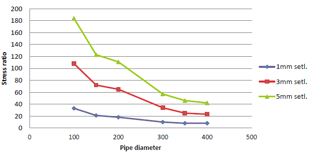
Smaller bore piping is more sensitive to thrust block settlement than larger bore piping, so flexible wrapping is most important for DN100 and DN150 pipe. Where soil near a concrete structure must be disturbed, new differential settlement may occur. The report then recommends wrapping the pipe in neoprene or polystyrene over some length, say 5 times the pipe diameter, immediately next to the structure. The wrapping increases pipe flexibility and decreases the stresses from differential settlement between the thrust block and the pipe.
Most differential settlement occurs immediately after installation and in the first few months of operation. After a few years it reaches an asymptotic value, and the pipe stress values do not increase further while the soil is left undisturbed. Continuing failures close to thrust blocks indicate that settlement is continuing, and action should be taken. The priority of each modification can be based on the failures observed in the field.
Frequently asked questions
Why were the vertical GRP risers overstressed in a buried fire water system?
In section D, the information received indicated that U-bolts fixed the dummy-leg supports of the carbon steel pipe to their base plates. This prevented upward expansion of the GRP riser, and the analysis gave an overstressed pipe. With guide and rest supports in place of the U-bolts, the stresses were 83% (sustained), 68% (operating) and 94% (hydrotest) of the long-term allowable stress.
How much thrust block settlement can DN100 and DN150 GRP pipe accept?
Roughly 3 mm for DN100 pipe and 5 mm for DN150 pipe before the pipe is overstressed. For 300, 350 and 400 mm pipe, settlement must exceed 5 mm. The settlement allowed in the individual small-bore sections ranged from ±1.5 mm to 5 mm.
When should flexible wrapping be applied to GRP pipe next to thrust blocks?
Where soil near a thrust block or other concrete structure must be disturbed, because new differential settlement may occur. The wrapping is neoprene or polystyrene over some length, say 5 times the pipe diameter, immediately next to the structure. It is most important for DN100 and DN150 pipe.