
A Commissioning Failure That Sent Debris Downstream
During commissioning of a natural gas compressor station, pieces of fibreglass fabric, mineral wool and steel wire were found throughout the downstream system. A small amount of mineral wool was also found in the surge valve. Inspection showed that the mineral wool found in the strainer came from the silencer in the recirculation line of the compressor. The silencer uses mineral wool (glass fibre) as damping material, held in place by a steel mesh, a fibreglass fabric cover and a perforated steel plate. The analysis covers one compressor train, the best documented case.
Internal inspection showed that the perforated steel plate was completely intact. The fibreglass fabric cover was torn and showed wear marks indicating repetitive stress on the fabric. The steel mesh was broken into pieces a few centimetres long, which were found downstream of the silencer in both the strainer and the surge valve. The loosening of the mesh and fabric allowed the mineral wool to be pulled through the perforated plate. These problems occurred in full recycling mode, when the flow through the silencer reaches its maximum. An inlet velocity of 40 m/s was adopted from site discussions and measurement data.
Vendor Velocity Rating and Gas Density
The vendor rated the silencer for a maximum of 60 m/s, reached by using a double layer of fibreglass fabric. The rating applies to non-turbulent conditions, whereas the flow in the field is highly turbulent. The vendor scaled the allowable velocity in proportion to the number of fabric layers, but dynamic pressure scales with the square of velocity. This suggests that at least four layers would be needed to sustain 60 m/s under non-turbulent conditions.
It is unclear whether the vendor took the operating gas density into account in its testing. The operating density is approximately 50 times that of atmospheric conditions, which gives dynamic pressures 50 times higher than with atmospheric air at the same velocity.
A Combined Experimental and CFD Approach
To find the root cause, small-scale laboratory tests were combined with computational fluid dynamics (CFD) simulations. The operating history showed only slow (quasi-static) transients from valve operation and compressor start-up, so pressure surges were considered unlikely and were not analysed. The work therefore concentrated on the flow pattern through the silencer.
The laboratory tests determined the order of magnitude of the pressure difference required to pull mineral wool through a perforated plate. Air was pumped through two plates, one with 3 mm holes at 5 mm pitch and one with 10 mm holes at 15 mm pitch, with mineral wool applied to the high-pressure side. The pressure difference was of the order of 200 mbar. Because the tests used atmospheric air, an equivalent pressure was calculated for gas at 50 kg/m³ from F ∝ ρAU², where F is the force on the wool particles, ρ the density, A the hole area and U the velocity. With a density ratio of 50 and the same velocity, the same force is obtained with laboratory holes 7 times larger in diameter than the field holes, so the 3 mm field holes correspond to 21 mm holes in the laboratory.
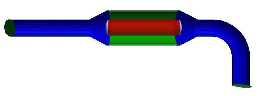
A preliminary CFD study showed that the bend closest to the silencer dominates the inlet flow profile over the more upstream bend. This is related to the 3.8 m axis-to-axis distance between the bends and to every bend forcing the main flow radially outward, which produces an asymmetric flow virtually regardless of the preceding piping. The final model therefore contains the closest bend, the silencer and a straight section downstream.
The damping material was modelled as a porous medium using Darcy-Forchheimer theory, with an assumed mineral wool density of the order of 50 kg/m³, a void fraction of 0.98 and a particle size of 10 µm. The central body of the silencer (the ‘cigar’) was also modelled as a porous medium, with solid end caps. The gas was methane at 49.74 kg/m³, 70 barg and 30 °C. The operating gas is not purely methane, but the deviations are small and have a negligible effect on the CFD calculations. Boundary conditions were a fixed inlet velocity, a fixed outlet pressure and turbulent wall functions. Steady-state analyses covered inlet velocities of 5 to 40 m/s, giving Reynolds numbers from 8.7×10⁶ to 6.9×10⁷ based on the pipe internal diameter. The transient analysis used 40 m/s.
What the Tests and Simulations Revealed
Under atmospheric conditions, hardly any mineral wool was drawn through the holes of plate 1 (3 mm). With plate 2 (10 mm) at the same net pressure difference, the mineral wool was drawn through more easily, and 10 mm holes were sufficient at 200 mbar. The laboratory force with 10 mm holes is 4.5 times smaller than the field force on 3 mm holes (50 × (3/10)² = 4.5). The equivalent field pressure difference for the 3 mm perforated plate is 200 mbar / 4.5 = 44 mbar, which is enough to pull the mineral wool through.
The inspection report contains a photograph showing a perforation diameter of the order of 10 mm, larger than the 3 mm on the silencer drawing. This larger perforation increases the movement amplitude of the fibreglass fabric relative to 3 mm holes, which increases wear of the fabric and fatigue of the steel wire.
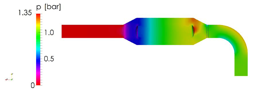
Steady-state results are reported for 5 and 40 m/s, as intermediate velocities gave similar results. The velocity distribution does not change significantly with the average velocity; only its magnitude scales with the inlet velocity. The bend induces an asymmetric velocity profile at the silencer inlet, with the largest asymmetry in the first 40 cm of the silencer. The highest flow differences were observed there, which makes it the most likely place for mineral wool to be pulled out of the perforated enclosures. The CFD velocities did not exceed the vendor’s specified maximum of 60 m/s, although that maximum is based on non-turbulent conditions. At 40 m/s the pressure drop across the silencer was approximately 0.9 bar. This is an indication of the field value, which might deviate slightly owing to uncertainties in the turbulence model and the porous medium model.
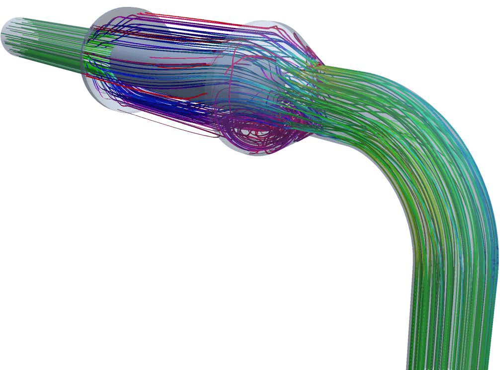
The streamlines show a turbulent region in the lower part of the silencer inlet, caused by the asymmetric inlet flow. This turbulence might lead to vibrations in pressure and so to movement of the fibreglass fabric and steel wire. Such movement might wear the fabric, for example at the edges of the perforated plate, and cause fatigue in the steel wire.
The transient analysis at 40 m/s showed pressure fluctuations of the order of 1 mbar peak to peak. Owing to the output time resolution, only a minimum frequency of 200 Hz can be given for this fluctuation.
Effect of Velocity and Remedies for the Silencer
At 5 m/s instead of 40 m/s the flow profile does not change significantly, and the Reynolds number (8.7×10⁶) remains far in the turbulent regime. Fabric failure is therefore likely at lower velocities as well. Fabric movements would probably be of smaller amplitude and frequency, so a lower velocity would likely prolong fabric life through a lower wear rate.
The report makes five recommendations.
- First, relocate the silencer several pipe diameters downstream, so that the unsteadiness and irregularities in the flow can recover before it enters the silencer. The asymmetric flow induced by the bend can persist over at least several pipe diameters.
- Second, modify the internals by shortening the ‘cigar’, which gives more uniform flow development before the damping material, or by reducing its diameter, which lowers the gas velocities.
- Third, use a denser, tougher mineral wool, which is presumably more resistant to pressure differences caused by flow instabilities.
- Fourth, decrease the perforation hole diameter to limit the forces on the fabric, the fabric movement amplitude and the resulting wear and fatigue. This does not change the turbulent zones, so it probably only reduces the rate of wear.
- Fifth, as an alternative, the damping material may be removed if the flow-induced noise is acceptable.
Correspondence with the client indicated that field tests by other parties showed compliance with external noise regulations with the damping material removed and additional sound insulation on the exterior. Detailed CFD studies might be necessary to optimise the relocation and the internal modifications.
Frequently Asked Questions
How much pressure does it take to pull mineral wool through a perforated silencer plate?
In laboratory tests with atmospheric air, mineral wool was drawn through a plate with 10 mm holes at a pressure difference of the order of 200 mbar. Hardly any was drawn through a plate with 3 mm holes. Scaled to gas at 50 kg/m³, the equivalent field pressure difference for the 3 mm perforated plate is 200 mbar / 4.5 = 44 mbar, which is enough to pull the mineral wool through.
Why is a 60 m/s silencer velocity rating not enough on its own?
The vendor’s 60 m/s rating was reached with a double layer of fibreglass fabric and applies to non-turbulent conditions, whereas the field flow is highly turbulent. The vendor scaled the allowable velocity in proportion to the number of fabric layers, but dynamic pressure scales with the square of velocity, which suggests at least four layers would be needed. The operating gas density is approximately 50 times that of atmospheric conditions, so dynamic pressures are 50 times higher than with atmospheric air at the same velocity.
How does an upstream bend affect flow into a silencer?
In the CFD model the bend induces an asymmetric velocity profile at the silencer inlet. The largest asymmetry is in the first 40 cm of the silencer, the most likely place for mineral wool to be pulled out of the perforated enclosures. The asymmetric flow can persist over at least several pipe diameters, so relocating the silencer several pipe diameters downstream is the first recommendation, and detailed CFD studies might be necessary to optimise it.