
At the Utorogu Flow Station in Nigeria, vibration was observed in the suction header, the discharge header and the pump recirculation line. Dynaflow Research Group performed pulsation, mechanical response and static stress analyses to find the root cause, identify any other possible problems and recommend improvements.
The station pumps crude oil from a surge vessel to a metering skid using three operational reciprocating pumps and one installed spare (3+1 arrangement). Crude passes through a 20 inch suction header to the pumps, and downstream of the pumps flows through an 8 inch discharge header towards the metering skid. A 4 inch recirculation line with a throttling valve connects the discharge and suction systems, and the valve is operated to hold the surge vessel level and pressure constant.
Three problems had been encountered. Both headers vibrated while the pumps were running, including after the lines were de-sanded. The recirculation line vibrated continuously, and the vibration levels affected the structural integrity of the throttling valve and its actuator, so station personnel resorted to manual operation of the valve. A leak was also observed at the welded joint between the recirculation line and the discharge header.
Linked Static, Pulsation and Mechanical Response Modelling
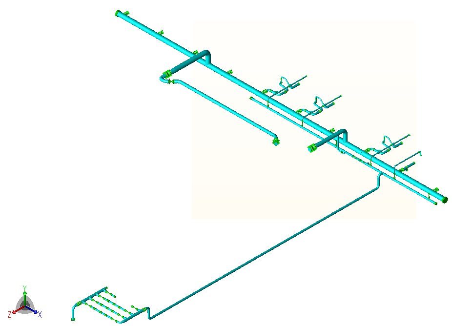
A static stress model was built first in CAESAR II from general arrangement drawings, site photographs and communication with site engineers, and served as the baseline for the pulsation model. The static analysis followed ASME B31.3 for low carbon steel A106 grade B, with the standard wall thickness reduced by the 3 mm corrosion allowance. The sustained case combined dead weight and pressure, 18.26 barg on the suction side and 96 barg on the discharge side, based on the rating of the piping. The expansion case applied the design temperature of 80 degrees Celsius.
The pulsation model, built in BOSfluids, contained the suction and discharge headers and all branch connections to the pumps. The pumps were represented by periodic positive displacement boundary conditions defined from the number of cylinders, stroke and cylinder size, and calculated pulsation levels were compared with the allowable values in API 674.
The pressure amplitudes were converted into unbalanced harmonic forces for a CAESAR II harmonic response analysis of the above-ground piping at the pump bays, with the buried sections assumed to be restrained sufficiently by the soil. The resulting dynamic pipe stresses were compared with fatigue values for the pipe material, because material fatigue is the structural failure mechanism of pulsation-related vibration.
Static Stress Analysis of the As-Built Layout
The expansion case showed no overstressed locations. In the sustained case, the stress exceeded the allowable at the connection of the recirculation line to the discharge header, reaching 160 percent of the allowable, and at the discharge of pump bay 5, reaching 122 percent. These high sustained stresses appear mainly to result from the inadequately supported discharge header, whose support spans are considered too large for a system subject to dynamic loads. The header sags under its own weight, and the stresses are high mainly in the recirculation line and some pump connections, which cannot move downwards with it. A site report records flanges at one joint resting on the ground and having broken through the concrete flooring.
The highest static stress was at the connection of the recirculation line to the discharge header, the joint at which the leak was observed. The leak might be partly due to fatigue from vibration of the discharge piping, and the high static stress may also have reduced the allowable number of alternating stress cycles.
Pulsation Analysis to API 674
The three operating pumps run at 47, 212 and 229 RPM, so three separate API 674 calculations were performed, each covering the first 15 multiples of the base frequency (RPM divided by 60). The allowable peak-to-peak pulsation for each frequency component falls as inner diameter and frequency increase, and on the suction side is also limited to 1.5 times the difference between average suction pressure and vapour pressure. On the discharge side of every pump, the pressure amplitudes remained well below the allowable. On the suction side, the allowable was exceeded at several locations between the suction header and each pump, for each pump speed. The suction allowable depends on the low mean line pressure at that location. A pulsation dampener of the type fitted on the discharge side of pump bays 3, 5 and 6 can address the exceedances.
Harmonic Force and Mechanical Response Analysis
The client had not reported the unbalanced forces, so an internally developed program calculated them between pairs of bends from the API 674 pressure amplitudes. The harmonic forces are typically between 100 and 1000 newtons because the wave speed in the fluid is approximately 1200 metres per second, so the pressure wavelength is typically many times the length of a straight pipe section. The maximum force found for each bend pair was applied at all of the first 15 multiples of the base frequency, with half at each bend. This is conservative, because the actual force typically decreases with increasing frequency.
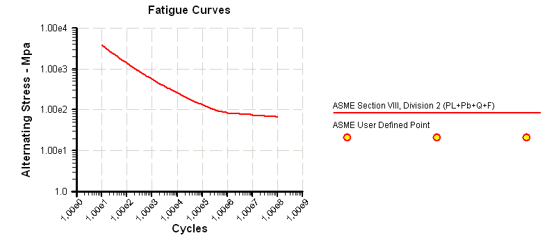
The allowable alternating peak stress is about 56.7 MPa, taken from the ASME VIII Div. 2 curve for SA-106 Gr. B at approximately 2.4·10⁹ cycles, the maximum number in a 20 year life, reached at 229 RPM. The curve includes a safety factor of 2 on stress and 20 on the number of cycles. The stress amplitude exceeded this allowable at all three speeds in the as-built system, and at 212 and 229 RPM with the modified supports before the suction header guides described below. At 47 RPM the as-built maximum was 100.4 MPa at node 620, against 38.8 MPa with the modified supports. At 212 and 229 RPM the highest amplitudes occurred at the tees at nodes 840 and 780. At node 840 the amplitudes were 60.2 MPa (212 RPM) and 113.6 MPa (229 RPM) as built, and 79.6 MPa and 113.4 MPa with the modified supports. The amplitudes at these tees result from a vibration mode of the suction header. The analysis concludes that this mode most likely does not occur on site: it requires the shaking forces to overcome friction at the rest supports, and site reports do not mention vibration of the suction header.
Support Modifications and Stress Verification
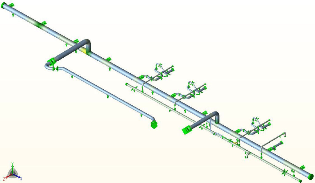
Support modifications at 13 locations are recommended, three modified and ten added. Static restraint loads are given for 11 of them; the other two, the guides described below, were found necessary to bring dynamic stresses below the fatigue limit. The modified arrangement replaces all existing supports on the discharge header with supports of different functions, including an axial stop that must be close to the branch leading to the metering skid because thermal expansion must be accommodated in the relatively short segment of pipe still above ground. In the sustained case, the modified arrangement gives lower stress throughout, and regularly spaced supports on the discharge header shorten the support span and reduce its stresses.
On the recirculation line, clamps are replaced by flange shoes bolted to a flange, and the slender pylons by properly sized structural steel carrying a 3-way stop and a rest support. Supports are also added on the piping connecting the discharge of the EMSCO pump in bay 2 to the discharge header, and the support over the fire wall in the long supply branch of the suction header receives an axial stop function. With the modified support arrangement, the sustained stress in the recirculation line is 62 percent of the allowable.
To remove the suction header vibration mode, guide function is added to the rest supports at nodes 729 and 860. These guides reduce the maximum alternating stress amplitude to 45.2 MPa at 229 RPM, below the 56.7 MPa allowable and below the endurance limit, so the fatigue damage accumulated in the as-built situation is not further increased.
The cumulative stress, the sum of the maximum stresses at all considered frequencies at a location, was also checked against the yield stress of about 224 MPa for SA-106 Gr. B at 80 degrees Celsius. It exceeded the yield stress only in the as-built system at 47 RPM (225.8 MPa at node 620). In all other cases it was below the yield stress.
Limits of the Analysis
The approach is conservative because the maximum pressure amplitude is assumed at all frequencies and the maximum harmonic forces are assumed to act at all frequencies, at all times and together. After the leak was repaired, the corresponding pipes were flushed and de-sanded, so it is difficult to reproduce the flow conditions that induced the vibrations. Not all observed failures due to vibration could be reproduced, possibly because of uncertainty in the support arrangement or other sources of vibration outside the scope, such as vortex shedding.
Frequently Asked Questions
Why did the joint between the recirculation line and the discharge header leak on a reciprocating pump station?
The analysis found a sustained stress of 160 percent of the allowable at the connection of the recirculation line to the discharge header, the highest static stress in the model. These high sustained stresses appear mainly to result from an inadequately supported discharge header, whose support spans are considered too large for a system subject to dynamic loads. The leak might be partly due to fatigue from vibration of the discharge piping, and the high static stress may also have reduced the allowable number of alternating stress cycles.
How is pump pulsation checked against API 674 for a reciprocating pump piping system?
A separate API 674 calculation is run for each pump speed, here 47, 212 and 229 RPM, each covering the first 15 multiples of the base frequency (RPM divided by 60). The allowable peak-to-peak pulsation for each frequency component falls as inner diameter and frequency increase, and on the suction side it is also limited to 1.5 times the difference between average suction pressure and vapour pressure. The discharge side remained well below the allowable, the suction side exceeded it at several locations for each pump speed, and a pulsation dampener of the type fitted on the discharge side of pump bays 3, 5 and 6 can address the exceedances.
What alternating stress amplitude is allowable for SA-106 Gr. B piping at 2.4·10⁹ cycles, and was it exceeded?
The allowable alternating peak stress is about 56.7 MPa, from the ASME VIII Div. 2 curve for SA-106 Gr. B at approximately 2.4·10⁹ cycles, the maximum number in a 20 year life, reached at 229 RPM. The curve includes a safety factor of 2 on stress and 20 on the number of cycles. The amplitude exceeded the allowable at all three speeds as built, and at 212 and 229 RPM with the modified supports before the suction header guides. With the two guides, the maximum is 45.2 MPa at 229 RPM, below the allowable and below the endurance limit.