
Condensate Forwarding Duty at a Nigerian Gas Plant
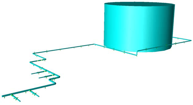
At a gas plant in Nigeria, four reciprocating pumps on an N+1 philosophy (three running, one spare) forward condensate from a storage and separation tank into a gas pipeline. A 12-inch suction header carries the condensate from the tank to the pumps, and a 10-inch discharge collector delivers it into the pressurised 24-inch gas line. The suction and discharge piping suffered severe vibration, and the discharge header was observed shaking on site. Pressure waves in the piping produce unbalanced forces. These forces cause piping vibration, which may result in high pipe stresses and metal fatigue. The assessment aimed to establish the root cause of the vibration and to identify options for improving the dynamic behaviour of the piping.
Assessing the System Against API 674 Design Approach 2
The assessment followed API 674 design approach 2, in which an acoustical simulation is combined with a mechanical response analysis. Predicted pulsation levels were compared with the allowable levels in paragraph 3.6 of API 674.
The piping was modelled in CAESAR II and imported into BOSfluids. The fluid model included the reciprocating pumps and the dampener bottles, which suppress the pressure peaks generated by the pumps. The as-built isometrics contained a considerable number of dimensional mismatches and type errors. Assumptions were made for missing or conflicting information and are marked on the isometrics. The results depend on those assumptions.
From Pulsation Time Histories to Harmonic Forces
Two dampener conditions were analysed with three pumps running at 283 RPM. In the properly filled condition, each 9.54 litre dampener bottle held 0.0085 cubic metres of gas. In the second condition, the suction bottles held no gas and the discharge bottles held 1 litre (0.001 cubic metres) of gas.
BOSfluids gave the time history of the unbalanced force on each straight pipe section between an elbow pair, and only the sustained vibration after start-up was used. Fourier decomposition of each time history gave the dominant frequencies and their force amplitudes. The five-cylinder pumps operate at 23.7 Hz, and 47 Hz is the tenth harmonic of the pump rotation frequency.
In the suction system with gas-filled bottles, the main contribution was at 47 Hz, with a further contribution at 3 Hz at the nodes immediately after the bottles. The report considers the 3 Hz component likely to come from the bottles. With no gas in the suction bottles, the 3 Hz component was absent, and the frequencies selected for analysis were 23.7, 30, 47, 87 and 94 Hz. In the discharge system, the dominant frequencies were 24 Hz and 47 Hz in the header pipe and 192 Hz in the smaller pipe sections, for both gas fills. The force amplitudes were higher with 1 litre of gas.
Each harmonic force was applied separately in CAESAR II with the as-built supports.
Pulsation Compliance, Fatigue, Vibration Levels and Support Modifications
With properly gas-filled bottles, pulsation amplitudes were within the API 674 allowable at all elements and harmonics in both the suction and discharge systems. With no gas in the suction bottles, the allowable was exceeded at some elements for some harmonics, mainly the tenth harmonic at about 47 Hz. With 1 litre of gas in the discharge bottles, the allowable was exceeded in many pipe segments, especially at the tenth harmonic (47 Hz), and the discharge system did not meet API 674.
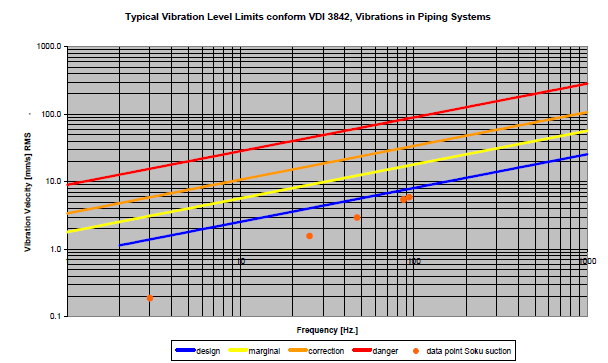
With properly filled suction bottles, the 3 Hz component coincided with a natural frequency of the system. The resulting resonant response gave a stress amplitude of 5.6 MPa at node 280, against the occasional allowable stress amplitude of 183 MPa. The largest displacement was 0.56 mm between nodes 320 and 340. VDI 3842 gives limit curves of vibration velocity against frequency, labelled design, marginal, correction and danger. According to VDI 3842, this vibration needs correction.
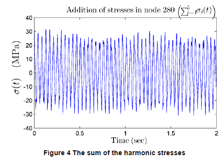
With no gas in the suction bottles, the largest stress amplitude from a single harmonic was 24.1 MPa at node 280 at 23.7 Hz. At that node, the amplitudes at 23.7, 30, 47, 87 and 94 Hz were 24.1, 2.4, 1.4, 0.4 and 4.2 MPa. Their sum, about 33 MPa, is the maximum that the combined stress can reach, and the fatigue assessment uses it. Over 20 years at 23.7 Hz, the metal at node 280 is exposed to this amplitude for 1.5 × 10¹⁰ cycles. The material fatigue curve gives an allowable stress amplitude of 27.5 MPa for that number of cycles. Taking the sum as about 33 MPa, the allowable is exceeded by about 20%. The fatigue curve includes a design safety factor of at least 2 and a factor of at least 15 on cycles, whichever is limiting. Because of these safety factors, the report states that the system might or might not fail. According to VDI 3842, the 24 Hz level needs correction and is close to the danger limit.
In the discharge system with the as-built supports, VDI 3842 levels were low with properly filled bottles. With 1 litre of gas, the 47 Hz level was in the danger zone and needs correction.
The report proposes additional or changed supports for both headers. In the suction header, the lowest natural frequency rises from 0.25 Hz with the original supports to 8.2 Hz. The modified systems were analysed with the forces from the properly gas-filled case. In the modified suction system, the 3 Hz stress amplitude was 0.02 MPa, compared with 5.6 MPa with the original supports. Displacements in the modified suction system were of the order of micrometres, and VDI 3842 gives acceptable levels for amplitudes up to 10 μm at any frequency. In the modified discharge system, the largest stress amplitude was 1.3 MPa, at node 5700 at 24 Hz, and the largest displacement was 0.1 mm at node 5729. All stress amplitudes in the modified systems are below the 183 MPa occasional allowable.
Dampener Gas Charge, Support Arrangement and As-Built Records
Three findings follow.
- First, API 674 compliance in both systems depended on the gas charge in the dampener bottles. With no gas in the suction bottles, the combined stress amplitude at node 280 exceeded the fatigue allowable by about 20%, and the system might or might not fail because of the safety factors in the fatigue curve. Maintaining the dampeners and checking the gas fill regularly is recommended.
- Second, pipe sections carried on rest supports only can resonate at low frequencies that are easily excited. In the suction header, the proposed additional supports raise the lowest natural frequency from 0.25 Hz to 8.2 Hz.
- Third, the analyses did not identify a root cause for the severe vibration observed on site. It may result from differences between the as-built drawings and the installed supports.
Frequently Asked Questions
What happens to API 674 pulsation compliance if the dampener bottles lose their gas charge?
With properly gas-filled bottles, pulsation amplitudes stayed within the API 674 allowable at all elements and harmonics in both the suction and discharge systems. With no gas in the suction bottles, the allowable was exceeded at some elements, mainly at the tenth harmonic at about 47 Hz. With 1 litre of gas in the discharge bottles, the allowable was exceeded in many pipe segments, and the discharge system did not meet API 674.
How is fatigue assessed for reciprocating pump piping vibration in CAESAR II?
BOSfluids gives the time history of the unbalanced force on each straight pipe section between an elbow pair. Fourier decomposition identifies the dominant frequencies, each harmonic force is applied separately in CAESAR II, and the stress amplitudes are summed. The sum is compared with the allowable stress amplitude from the material fatigue curve for the number of cycles. At node 280 the sum is about 33 MPa against an allowable of 27.5 MPa for 1.5 × 10¹⁰ cycles over 20 years, an exceedance of about 20%. The system might or might not fail because of the safety factors in the fatigue curve.
Why do rest supports give low natural frequencies in pump piping, and how are they corrected?
Pipe sections carried on rest supports only can resonate at low frequencies that are easily excited. In the suction header, the proposed additional supports raise the lowest natural frequency from 0.25 Hz to 8.2 Hz. The 3 Hz stress amplitude falls from 5.6 MPa with the original supports to 0.02 MPa with the additional supports.