
Severe Vibration in Vaporiser Feed Pump Piping
The suction and discharge piping connected to the quadruplex methanol vaporiser feed pumps was suffering from severe vibration. A pulsation analysis combined with a mechanical response analysis of the as-built piping was performed to establish the root cause. The analyses determined the stress and displacement levels resulting from the shaking forces induced by the pressure pulsations, and recommendations for improvement were made on the basis of the results.
Pulsation and Response Analysis to API 674 Design Approach 2
The system was analysed for compliance with API 674 design approach 2, in which the system is assessed by an acoustical simulation in conjunction with a mechanical response analysis. The predicted pulsation levels were compared with the allowable levels in paragraph 3.6 of API 674. The allowable peak-to-peak level of each pulsation component depends on the pipe inside diameter and the pulsation frequency.
Exceedance of the allowable levels on a limited number of frequency components could be considered acceptable, for instance if the combined pressure (static plus pulsation) stays within the levels that affect the pressure containment capability of the pipe, and the stress and vibration levels resulting from the shaking forces stay below the levels that affect its structural integrity. The piping system is then fit for purpose. The shaking force time history on each straight pipe section between an elbow pair, a result of the pulsation analysis, was used in the mechanical response analysis to assess the stress and vibration condition.
Model, Load Case and Analysis Method
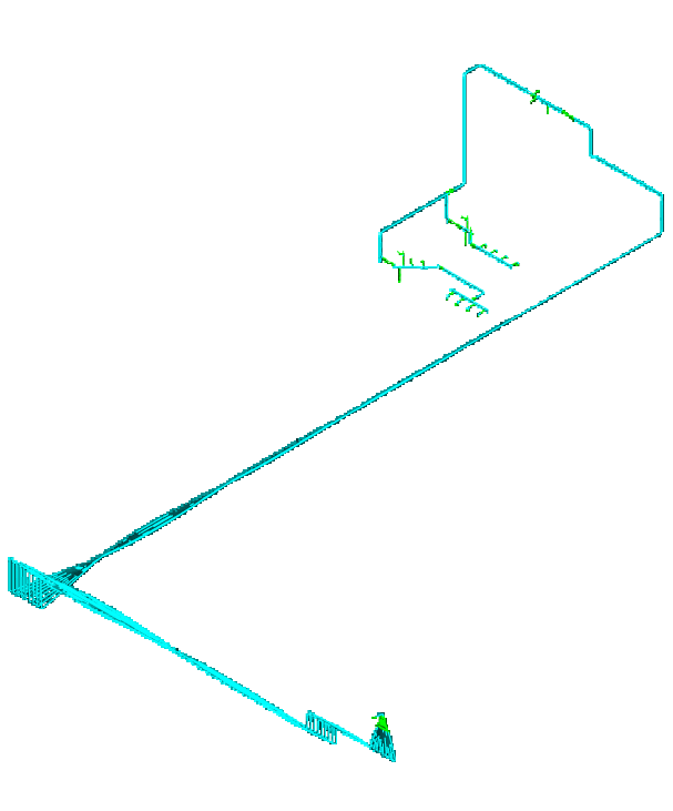
The as-built suction and discharge piping configuration was modelled in CAESAR II and the model was imported into the BOSfluids fluid simulator. The quadruplex pumps and the pulsation bottles were included in the fluid model. The load case for both systems was one pump running at maximum speed (196 rpm) at full capacity.
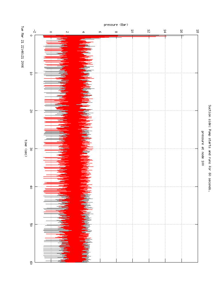
In the simulation the system is started instantaneously at time zero. The system starts with large fluctuations, and it takes a number of seconds before the shocks related to the instantaneous start have been dissipated by viscosity and a full harmonic steady state is reached. Start-up is a temporary (occasional) phenomenon, so its effect on the pulsation levels and shaking forces was neglected in the assessment of the sustained vibration and stress levels, and the first few seconds were excluded from the study.
In a first step of the mechanical response analysis the natural frequencies were determined and inspected for obvious mechanical resonances. Support stiffness is important for the dynamic behaviour, so the stiffness of a number of essential supports (the axial stops) was determined and included in the model. In a next step a time history simulation based on the shaking force time histories from the pulsation analysis was performed to determine the stresses and displacements.
Pulsation, Natural Frequency, Stress and Time to Failure Results
For both systems the pressure levels in the piping exceeded the allowable levels in API 674 at the 4th, 8th and 12th harmonics. A Fourier decomposition of the shaking forces showed a dominating peak at 13 Hz, corresponding to the 4th harmonic of the pump speed, in both systems.
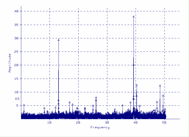
In the suction system the lowest natural frequency was 16.7 Hz, above the 13 Hz peak in the excitation force at the 4th harmonic. Clear resonance was apparently not applicable. The maximum dynamic stress level in the main piping was 218 MPa at node 100, and the maximum displacement was 8 mm at node 39. The 218 MPa allows for 10⁶ cycles. Taking into account the safety factor of 20 on cycles included in the fatigue curves, failure was to be expected in 20 days at a basic stress frequency of 13 Hz. Dynamic stresses at this level definitely affect the structural integrity of the system.
In the discharge system the lowest natural frequency was 3.3 Hz and 20 mode shapes lay below the 4th pump harmonic, so mechanical resonance most probably occurred. The maximum dynamic stress level in the main piping was 170 MPa at node 4005 (pump manifold), and the maximum displacement was 17 mm at node 570. The 170 MPa allows for 10⁸ cycles. Taking into account the safety factor of 20 on cycles included in the fatigue curves, failure was to be expected in 2000 days at a basic stress frequency of 13 Hz. The effect of mechanical resonance was limited, but the stress levels were not acceptable for long term undisturbed operation.
In both systems the results showed high stresses at small bore connections.
For one pump running at maximum speed at full capacity, the expected time to failure at the maximum stress level in the main piping was 20 days for the suction system and 2000 days for the discharge system.
Recommendations to Reduce Pulsation and Dynamic Stress
Reduction of the pulsation levels in both the suction and discharge systems is required. It can be achieved by increasing the size of the pulsation bottles and moving them closer to the pump manifold. The small bore connections are to be braced back to the main line. The piping layout and/or support arrangement is to be changed to keep dynamic stresses within allowable (endurance) levels.
Frequently Asked Questions
What is API 674 design approach 2 for pump piping?
In API 674 design approach 2, the system is assessed by an acoustical simulation in conjunction with a mechanical response analysis. The predicted pulsation levels are compared with the allowable levels in paragraph 3.6 of API 674. The shaking force time histories from the pulsation analysis are used in the response analysis to determine stress and displacement levels.
How long can pump piping last at a dynamic stress of 218 MPa?
In the suction system studied, 218 MPa allows for 10⁶ cycles. Taking into account the safety factor of 20 on cycles included in the fatigue curves, failure was to be expected in 20 days at a basic stress frequency of 13 Hz.
How are pulsation levels and dynamic stress reduced in pump suction and discharge piping?
The pulsation levels are reduced by increasing the size of the pulsation bottles and moving them closer to the pump manifold. The small bore connections are braced back to the main line, and the piping layout and/or support arrangement is changed to keep dynamic stresses within allowable (endurance) levels.