
Weld 34 Crack and Dead-End Configuration
The circulation system has two pumps, one operating and one spare. The operating pump feeds cooling water back into the Benson vessel at the top of the system. In the situation analysed, one pump had been taken out for revision. A blind valve was placed at the location of the second pump and a dead-end was created. A pump trip usually causes a pressure wave through the system that, especially at a dead-end, might result in unbalanced forces. Node 2035 of the model is at the weld.
The crack was partly oxidised and showed four steps: initiation caused by the weld, a heavily oxidised step in which the crack was probably not caused quickly, and two quick crack steps. The weld is 15Mo3, which is less tough than the base material 1.6368 (WB36) from EN 10028 part 2. The base material has a minimum strain of 16%, which makes it very unlikely that the crack was caused by mechanical loads from slow processes such as thermal expansion. A stress intensification factor (SIF) of 2 was applied for the weld geometry. Inspection of the crack could neither confirm nor deny low-cycle fatigue (LCF).
CAESAR II and BOSfluids Model and Fatigue Assessment Basis
The relevant part of the system was first modelled in the pipe stress package CAESAR II and then imported into the transient software BOSfluids. The objective of the BOSfluids analyses was to determine the maximum system pressure that would occur. BOSfluids was used for the pump trip and pump start-up pressure analyses, and the dynamic module of CAESAR II for the mechanical response analysis of bending stresses caused by unbalanced loads that make the piping swing. Entrapped air or vapour was included in the analyses, and the pump trip case was repeated for several amounts of entrapped air or vapour at the dead-end.
For the fatigue assessment, the nominal stress according to AD Merkblatter 200 section S2 was multiplied by a factor of 2. This factor results from four components: temperature, fT = 0.88; static stress, fM = 0.83; thickness, fd = 0.99; and surface roughness, f0 = 0.7. The surface roughness factor is based on the observed roughness.
Thermal Bowing, Check Valve, Pump Trip and Start-Up Results
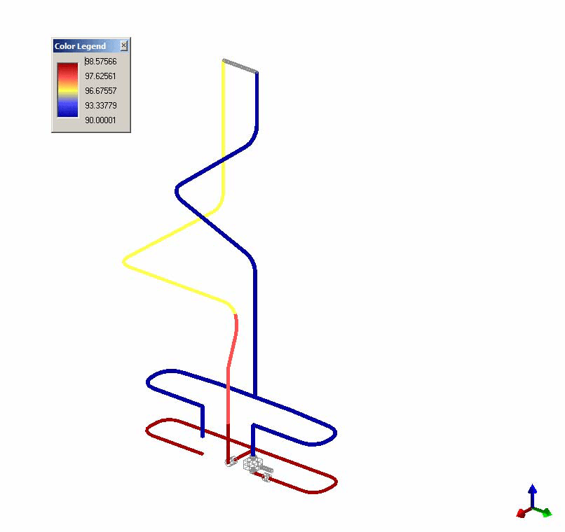
Thermal bowing results from cold fluid at the bottom of the pipe and hot steam or vapour in the top half. A maximum temperature difference of 290°C (320°C less 30°C) between the upper and lower sides of the pipe was assumed, and the resulting thermal stresses at the weld are 130 MPa. The failure mechanism for such thermal stresses is fatigue. With an SIF of 2, ASME Boiler and Pressure Vessel Code section VIII division 2 Appendix 5 gives allowable cycles of around 100,000. Thermal bowing is therefore unlikely to be the cause of the crack.
When the check valve near the pump closes slowly, the maximum back flow is 2.5 m/s. With the valve fully closed at the moment of maximum back flow, the pressure increase at weld 34 depends on the amount of entrapped air or vapour. Across seven cases (six volumes from 0.00125 m³ to 0.02 m³, and no vapour), the pressure increase was between 23 and 36 barg. This pressure increase is insufficient for the crack to occur, so the check valve is unlikely to be the cause.
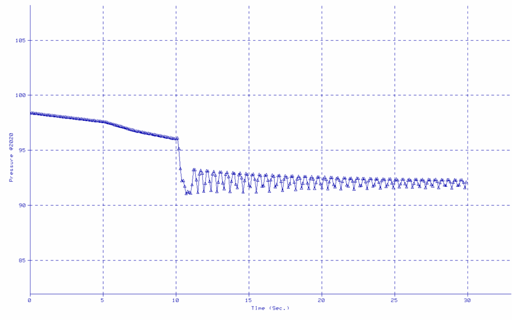
In the pump trip case, the maximum pressure at node 2035 depends on the volume of entrapped air, as theoretically predicted. At node 2020, in the vicinity of the cracked weld, the maximum pressure after the pump trip was between 92.7 and 93.3 barg across six entrapped volumes from 0.00875 m³ to 0.07 m³.
During pump start-up, the maximum pressures remain below the allowable pressure. The unbalanced forces on the manifold reach a maximum of 15 kN, which results in movement of the manifold but is insufficient for the crack to appear.
Mechanical Response Results for Pump Trip and Start-Up
The mechanical response analysis was made to assess the effect of LCF. A static flexibility analysis was performed first and showed that the static stresses for both operating and design conditions are within the allowable of the material. For the dynamic cases, the model was extended with supports and springs, the weights of the valves and pumps were added, and the pump trip and pump start-up time histories were used as input.
In the pump start-up case, the maximum bending stress at node 2035 is 27 MPa without the 5.5 kNm start-up couple and 29 MPa with it. The couple has its maximum only during the first 500 ms, and the highest bending stresses occur later. The start-up stress levels are lower than in the pump trip scenario and too low to justify the crack. One reason is that the unbalanced forces of the pump trip last longer than those of the pump start-up.
With the factor of 2 applied, the oscillating stress amplitude at node 2035 during pump start-up is 2 x 27 MPa = 54 MPa. Figure 12 of section S2, klasse K2, gives a range (Breite) of 108 MPa and an allowable number of 200,000 cycles for this amplitude. It is unlikely that the system experienced that number of cycles during the past year.
For the pump trip, the same assessment basis applies, and the dynamic simulation gives an oscillating stress amplitude of 233 MPa at node 2035. Figure 12 of section S2, klasse K2, gives a range (Breite) of 466 MPa and an allowable number of 3,000 cycles. Each pump trip corresponds to 10 to 15 stress cycles, so 3,000 cycles equal 200 to 300 pump trips. This number of pump trips might have occurred during the past year.
| Case | Oscillating stress amplitude (MPa) | Range, Breite (MPa) | Allowable cycles |
|---|---|---|---|
| Pump start-up | 54 | 108 | 200,000 |
| Pump trip | 233 | 466 | 3,000 |
Pump Trip Conclusion and Horizontal Stop Mitigation
The events and mechanisms analysed do not fully explain the observed failure of weld 34. The individual pump trip and pump start-up events result in pressures and unbalanced forces that are not sufficient for the failure to occur. The mechanical response analysis shows that 200 to 300 pump trips correspond to the allowable number of 3,000 cycles at the weld. LCF does not fully correspond with the detailed analysis of the crack, which seems to indicate four individual events, and LCF could not be ruled out as a cause. The analysis concludes that a series of pump trips over time is the most likely source of the failure. All other possible causes were investigated and are much less likely to be the source of the failure.
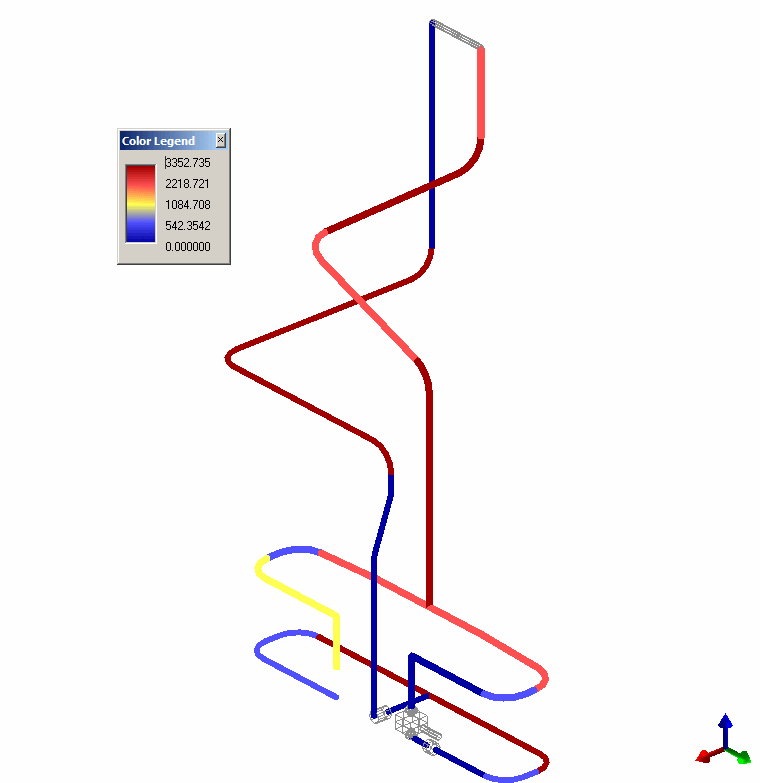
Measures can be taken to eliminate the mechanism considered responsible for the failure, which requires the possible swinging of the suction and discharge loops to be eliminated. This could be done by introducing a number of horizontal stops that maintain the left-right symmetry and do not restrain the necessary thermal expansion, which is achieved by the selection of the stop locations. If required, we can provide the necessary information and loads.
Frequently Asked Questions
How many pump trips correspond to the allowable fatigue cycles at weld 34?
An oscillating stress amplitude of 233 MPa and a range of 466 MPa give 3,000 allowable cycles. At 10 to 15 stress cycles per pump trip, that is 200 to 300 pump trips.
Can thermal bowing crack a weld in hot circulation piping?
A 290°C temperature difference gives thermal stresses of 130 MPa at the weld. With an SIF of 2, the allowable cycles are around 100,000, so thermal bowing is unlikely to be the cause of the crack.
How can swinging of pump suction and discharge loops be eliminated?
Horizontal stops can be introduced that maintain the left-right symmetry and do not restrain the necessary thermal expansion. The stop locations are selected to achieve this.