
Nitrogen Skid Stress Verification Requirement
A manufacturer produces a nitrogen metering skid for a project. As a result of a client performance requirement, the existing design had to be verified by stress analysis. The skid is a straight pipe configuration with valves and flow meters, supported approximately 1000 mm above the steel skid base frame. The pipe is supported from small portal-frame structures referred to as goal posts. The inlet and outlet flange connections are subject to external loads, and the client specification also imposes maximum deflection figures on the skid. The pipe stresses and the loads on the flanges were checked to ASME B31.3. The location and function of the supports formed part of the deliverables.
Flange Load Check on the 8-Inch ASME B16.5 Connections
A preliminary capability check of the 8-inch ASME B16.5 300# inlet and outlet flanges showed that the loads defined in the client specification were too large. The calculations concluded that the loads on the inlet and outlet flanges had to be reduced by 40% to comply with ASME B31.3.
CAESAR II Model of the Skid and Frame
The analysis used the pipe stress program CAESAR II, with the applicable steel frames included in the model. The skid-mounted pipe, including the external loads, and the steel structure were each assessed for stress and deflection. The assessment used a design pressure of 12 barg, a design temperature of 82 °C, an installation temperature of 5 °C and a pipe corrosion allowance of 1.6 mm. Wind loads did not have to be considered. The materials were SA-106 Gr. B for the pipe, SA-105 for the flanges, S235JR for the frame and grade 8.8 for the anchor bolts.
Nozzle Load Reduction, Seismic Acceleration and Load Cases
The inlet and outlet loads were reduced to 60% of the specified values, a reduction the client approved. The reduced loads are a radial force of 7,272 N, longitudinal and circumferential forces of 8,910 N each, a torsion moment of 9,690 Nm, and out-of-plane and in-plane moments of 6,852 Nm each. In its present geometry the skid cannot resist torsion moments, so the torsion moment was assumed to be transmitted from the upstream interface to the downstream interface and accommodated by the attached piping. After discussion with the client, the reduced loads were assumed to be generated 67% by thermal loads (secondary loads) and 33% by weight loads (primary loads), a commonly used differentiation. The load directions were selected to maximise the stresses in the pipe and the skid frame.
Seismic loads were determined to ASCE 7-05 from a short term acceleration Ss of 8.5% g and an importance factor of 1.25. SDS was 0.08, with Fa assumed as 1.4. The effective acceleration was calculated as 0.06 g using a dynamic load amplification factor of 2. A value of 0.085 g was used conservatively in the calculations.
Ten load cases, L1 to L10, were defined: hydrotest, operation, sustained, seismic acceleration in the X and Z directions, four occasional combinations and expansion. The nozzle load set used in the load cases excludes the torsion moment. The sustained case includes 33% of the nozzle loads and the expansion case 67%. The pipe stress check used L1, L3, L6 and L7 as primary cases and L10 as the secondary case. The frame stress check used L3, L6 and L7 as primary cases and L2 and L10 as secondary cases. Pipe support selection used the maximum of L2 to L10.
Goal-Post Frame Modifications and Support Selection
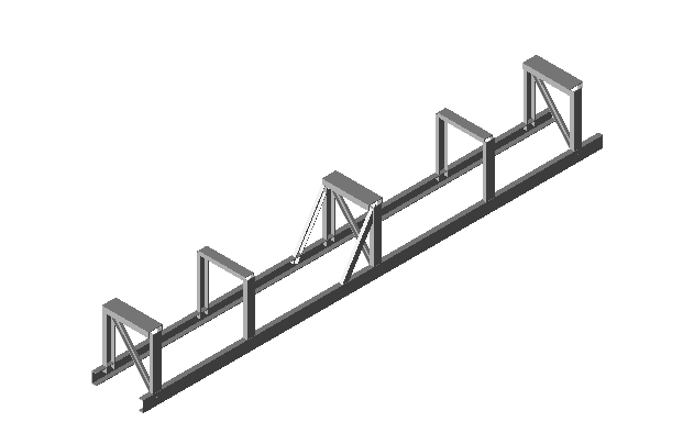
The frame stresses based on the original skid drawings were too large at several locations. To accommodate the loadings, several modifications are required. The horizontal beams of the mid and two outer goal posts are changed to UNP200. Diagonal UNP80 beams are added to the mid and two outer goal posts, and two diagonal UNP80 beams are added to the mid goal post. Rib plates are added inside the longitudinal UNP160 beams at the mid and two outer goal posts. Base and rib plates are added outside the UNP160 beams at the same locations (six in total) to accommodate the anchor bolts.
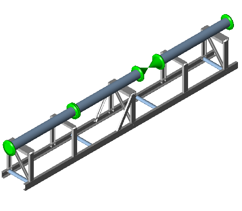
Directional and lateral support of the skid pipe is necessary to accommodate the loads on the inlet and outlet flanges. The selected support arrangement is four rest and guide supports and one 3-way stop, and U-bolts may be applied to support the pipe on the frame.
Anchor Bolt Sizing and Design Loads
The anchor bolts, located at the longitudinal UNP160 beams at the mid and outer goal posts, were sized with a conservative approach. For the three pipe supports, the maximum vertical load and the maximum lateral load were taken from the CAESAR II results. Each maximum value was imposed on all three supports. The maximum axial load on the mid pipe support defined the axial load. Two bolts at each goal post were assumed to accommodate the loads on that goal post. This gave design loads of 17 kN vertical and 15 kN lateral at the left, mid and right goal posts, plus 15 kN axial at the mid goal post. The selected bolts were 7/8-inch UNC grade 8.8 (yield stress 640 MPa, UTS 800 MPa), with an effective tensile area of 298 mm².
Verification Results for Pipe, Frame and Anchor Assembly
With the modifications implemented and the flange loads reduced by 40%, the pipe stresses comply with ASME B31.3, all stresses in the skid frame are acceptable for the given loads, and the pipe deflections are within the margins in the client specification.
The combined Von Mises stress was 106 MPa in the bolts at the left and right goal posts and 172 MPa in the bolts at the mid goal post. The maximum bolt stress was 172 MPa against an allowable of 267 MPa. The base plate is 80 × 70 mm and 12 mm thick. The maximum plate stress from the bearing, tearing and shear checks was 40 MPa against an allowable of 120 MPa.
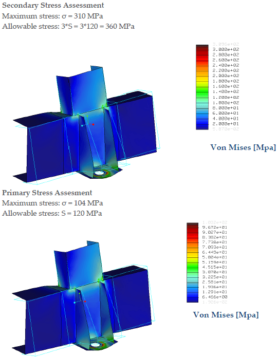
A finite element model of a single bolt and base-plate assembly with gusset plates was then used to check the local stresses. Primary and secondary loads were determined from the 67%:33% distribution, using the design loads listed above. The secondary stress assessment gave a maximum stress of 310 MPa against an allowable of 3S = 3 × 120 = 360 MPa. The primary stress assessment gave a maximum stress of 104 MPa against an allowable S = 120 MPa. The allowable stresses were based on the rules in ASME VIII Division 2, and all stresses were within the limits of this code.
Six 7/8-inch grade 8.8 anchor bolts are required to fix the skid to the foundation. The bolts should be located in a base-plate and rib assembly outside the UNP160 longitudinal beams, and washers are recommended underneath them.
Conditions and Scope of the Nitrogen Skid Verification
The verification assumes that the torsion moment is accommodated by the attached piping. The anchor bolts should be properly pre-tensioned. The design of the fixation of the anchor bolts to the foundation was not part of the analysis.
Frequently Asked Questions
How much did the flange loads have to be reduced for a nitrogen skid to meet ASME B31.3?
The specified loads on the 8-inch ASME B16.5 300# inlet and outlet flanges had to be reduced by 40% to comply with ASME B31.3. The skid was analysed with 60% of the specified values: a radial force of 7,272 N, longitudinal and circumferential forces of 8,910 N each, and out-of-plane and in-plane moments of 6,852 Nm each. The client approved the reduction. The skid cannot resist torsion moments, so the torsion moment was assumed to be accommodated by the attached piping.
How are thermal and weight loads split when checking skid nozzle loads?
The reduced nozzle loads were assumed to be generated 67% by thermal loads, treated as secondary loads, and 33% by weight loads, treated as primary loads. This was discussed with the client and is a commonly used differentiation. In the load cases, the sustained case includes 33% of the nozzle loads and the expansion case includes 67%.
What anchor bolts fix a nitrogen skid to the foundation, and are their stresses within the allowable?
Six 7/8-inch UNC grade 8.8 anchor bolts are required, with two bolts at each of the mid and two outer goal posts. They should sit in base-plate and rib assemblies outside the UNP160 longitudinal beams, with washers recommended underneath. The maximum combined Von Mises bolt stress was 172 MPa against an allowable of 267 MPa. The fixation of the bolts to the foundation was not part of the analysis.