Dynaflow Research Group (DRG) has performed a stress and surge analysis using BOSfluids at Rotterdam Maasvlakte on an extension to their firewater system to accommodate the loading of LNG onto ships and barges at the jetty area. The extension of the firewater system consisted of an underground glass-reinforced epoxy (GRE) main with new hydrants, monitors, and deluge systems. The water network is supplied from a dedicated fire station that consists of:
- Two jockey pumps
- Two electric firewater pumps
- One diesel firewater pump
The jockey pumps are present to maintain the pressure in the system between 8-9barg. Where fire water demand increases and the pressure in the system drops, the electric pumps will be started. Further, in the case of a power loss or double failure of the electric pumps, the diesel pump will start as soon as the pressure in the system drops below 6barg.
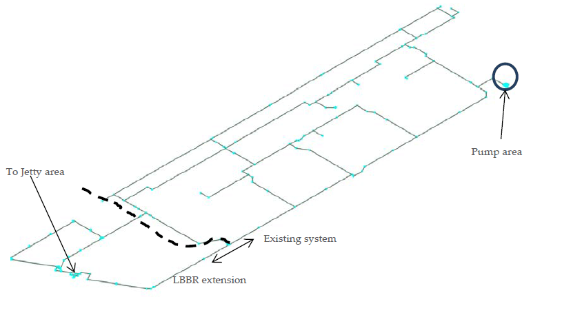
Figure 1 | Overview of LBBR firewater system.
System routing was modelled per supplied isometrics; the jetty area was not modelled in detail due to insufficient information. Instead, the effects of the jetty area piping on the system are accounted for by modelling the pressure loss that will occur in the jetty firefighting piping.
A static stress analysis was performed using CAESAR II for the system extension in accordance with ISO 14692. This stress analysis found multiple overstressed locations, with the following recommendations:
- Additional laminate thickness at and near multiple bend fittings
- Rest supports under headers within valve pits
- Reroute of piping to increase distance and improve flexibility between hydrants and valve pits
With these recommendations, the LBBR extension conformed to ISO 14692 with all GRE flanges remaining within allowable values.
For the surge analysis, the potential firefighting in the jetty area required the largest water demand of 17772.8 L/min with three hydrants demanding 2000L/min each; this was considered the worst-case scenario. Therefore, all surge cases were derived from this steady state condition. The following firewater cases are simulated for both an all flow path available and a singular flow path (that can occur due to maintenance) available event.
- Startup of the system during a fire in the Jetty area
- Start of a single electric pump
- Start of two electric pumps
- Emergency shutdown of a single electric pump
- Emergency shutdown of the diesel pump
- Conservative assessment of the number of hydrants able to simultaneously close over 1s
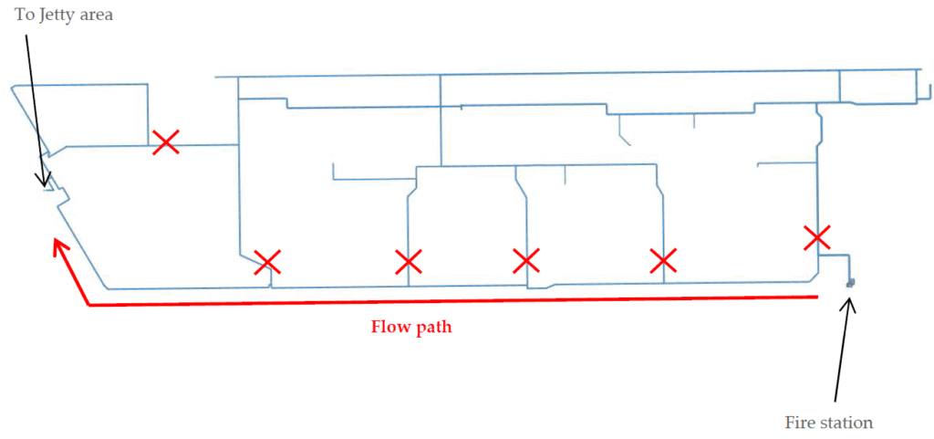
Figure 2 | Overview of single flow path system.
Figure 3 and Figure 4 show the hydrant closure assessment for both the all-flow path available and singular flow path available scenarios, respectively. The hydrants begin closure at t=3s with full closure at t=4s. It is found that when multiple hydrants are closed at the same time, the pressure peaks become higher. When only a single flow path is available, higher-pressure peaks are found alongside a smoother pressure wave profile due to fewer locations rebounding the pressure waves, leading to less constructive/destructive interference.
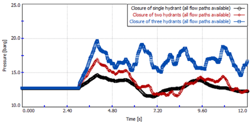
Figure 3 | Assessment of simultaneous hydrant closure with all flow paths available.
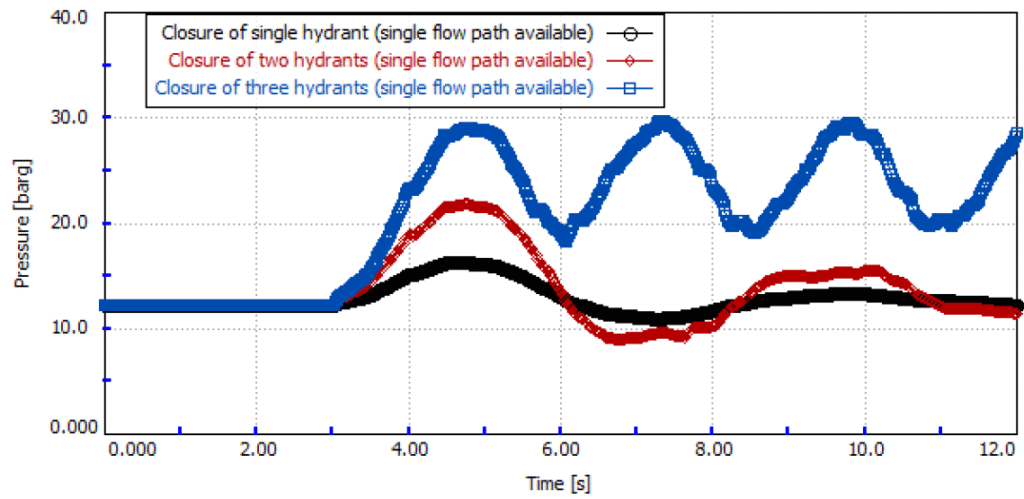
Figure 4 | Assessment of simultaneous hydrant closure with a single flow path available.
For aboveground piping, failure from surge often occurs due to a combination of axial and circumferential stresses from the internal pressure excess alongside the axial unbalanced forces. In buried piping, due to the well-restrained nature of the soil, the failure mechanism from surge is the circumferential stresses as a result of the pressure excess. In case the pipe is sufficiently restrained in the axial direction, it is sufficient to verify that the occasional surge pressure is less than 1.33 times the design pressure.
Within this analysis, the friction from the soil on the buried piping was evaluated against the unbalanced force buried derived from the surge analysis. The GRE piping was determined to be sufficiently restrained, and an allowable occasional pressure of 21.3barg was calculated. The surge study concluded that the pressure in all cases remained within the calculated allowable pressure, with the exception of when two or more hydrants were closed simultaneously, when a singular flow path was available. With DRG recommending that the closure time of the hydrants either be closed over a minimum of 4s or that the hydrants are to be closed consecutively and not simultaneously.
This project and the analysis thereof show the importance of considering your surge analyses not only for various upset scenarios but also for various states of your network. If your piping system requires flow-paths and locations to be isolated for maintenance or inspection, then these variations should be evaluated, as they can impact the results of your analysis and mitigation measures.