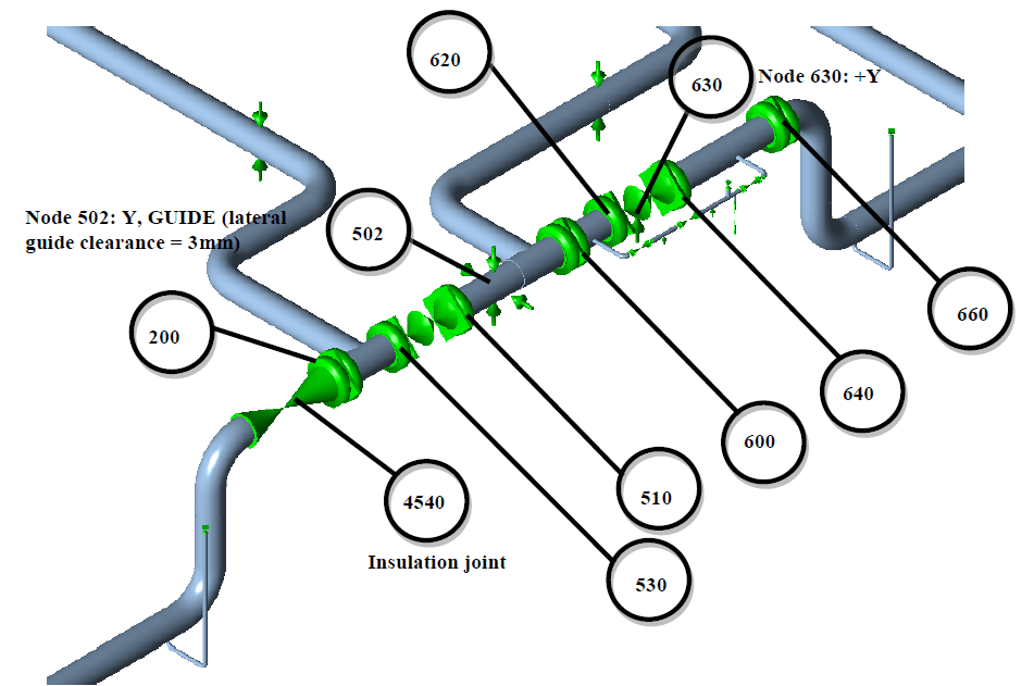
An additional separator was installed in Phase 2 of a cluster project and was to be connected to the existing lines through a modified above-ground (A/G) manifold. The manifold also connects to an existing buried (underground, or U/G) line. The analysis applied pressures of 100 / 225 Barg and temperature loads of -20°C / 0°C and 50°C.
In Phase 1 the existing A/G manifold was extended with a temporary spool, and a part of the connecting U/G line was excavated for that purpose. The Phase 2 arrangement connects the A/G manifold to the separator by means of an A/G pipe routing. The assessment covered the longitudinal stresses in the modified A/G manifold and in the connected existing U/G piping, and the loads on the connecting flanges, the insulation joint and the supports.
Flange and Insulation Joint Allowables
The flanges are ASME B16.5 WN RF 600# flanges, for which the allowable bending moment is 60 kNm. The allowable loads for the insulation joint were supplied by another party: 384 kNm for load cases L1 to L7 (defined below) and 315 kNm for the hydrotest. Stresses are reported as a percentage of the allowable stress. The material allowables and the determination of the allowable flange loads are defined in the main report for the project.
CAESAR II Model, Codes and Load Cases
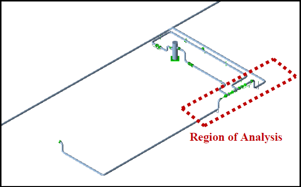
The analysis used CAESAR II. A part of the existing system was modelled to allow correct truncation. The A/G lines from the manifold to the separator were supplied by another party as a model part for truncation only. No stress analysis of those lines was performed. Their stress assessment is outside the scope and is analysed by that party. The stress calculations considered longitudinal stresses only, assessed to B31.3 for the A/G part and B31.8 for the U/G part. The client covered the circumferential stress assessment (internal pressure).
Eleven load cases from the main report were used. L1 and L2 are the hot and cold operation cases, and L3 is the sustained case, which includes primary loads only. L4 to L7 are four occasional cases, with wind in the X, -X, Z and -Z directions. L8 to L10 are three expansion cases: L8 covers 4°C to 50°C, L9 covers -20°C to 4°C and 0°C to 4°C, and L10 covers -20°C to 50°C and 0°C to 50°C. The eleventh case is the hydrotest, with a test pressure of 150 / 337.5 Barg. Stresses were analysed for soil models A and B, as defined in the main report.
Tee Piece Assumptions and Support Lift-Off
The two tee pieces in the manifold are designed to AD-Merkblatter and fabricated from P355NL1, which has an allowable stress at least equal to that of the plain pipe. In the analysis their material was not modified and was assumed equal to plain pipe, a conservative assumption. The total under-tolerance on the tee piece drawing is 3.2 + 1 = 4.2 mm, and was specified as a corresponding percentage mill under-tolerance with respect to the total wall thickness.
In the hot design case (L1), the pipe lifts off the rest support at node 630. An additional sustained case was therefore analysed without this support, to capture the primary stresses during hot design.
Stresses and Loads on Flanges, Insulation Joint and Supports
No modifications to the analysed isometric are required. All longitudinal stresses in the A/G manifold are within the Stresses and Loads on Flanges, Insulation Joint and Supportsallowable limits, and no excessive stresses were found in the connecting U/G lines. Table 1 gives the highest stress per load case for soil model A, as a percentage of the allowable stress.
| Case | Highest stress (% of allowable) | Node |
|---|---|---|
| L1 hot operation | 42 | 4501 |
| L2 cold operation | 35 | 4501 |
| L3 sustained | 49 | 502 |
| L4 wind X | 37 | 502 |
| L5 wind -X | 37 | 502 |
| L6 wind Z | 37 | 502 |
| L7 wind -Z | 37 | 502 |
| L8 expansion | 32 | 4529 |
| L9 expansion | 8 | 4530 |
| L10 expansion | 39 | 4530 |
| Hydrotest | 46 | 4498 |
Table 1: Highest stress per load case, soil model A
For soil model A, the highest stress over L1 to L10 was 49%, in the sustained case (L3) at node 502. The highest stresses for soil model B are equal to or lower than those for soil model A in cases L1 to L10. In the additional sustained case, without the support at node 630, the maximum stress was 56% of the allowable stress at node 502.
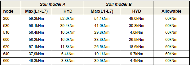
Maximum loads were checked at seven flange nodes against the 60 kNm allowable. The loads at all seven nodes are within the allowable for L1 to L7 and for the hydrotest, in both soil models. The axial load was ignored in the flange and insulation joint analysis, since it is either compressive or contributes negligibly to the equivalent pressure.
At the insulation joint (node 4540), the maximum load over L1 to L7 was 52.9 kNm in soil model A against an allowable of 384 kNm, and the maximum hydrotest load was 38.1 kNm in soil model B against 315 kNm.
Maximum vertical loads are reported for the two supports for verification. The supports are node 502 (Y, guide with a lateral clearance of 3 mm) and node 630 (rest support, +Y). At node 502 the maximum vertical loads were -81 kN over L1 to L7 and -79 kN in the hydrotest, both in soil model B. At node 630 they were -47 kN over L1 to L7 and -42 kN in the hydrotest, both in soil model A. A negative value indicates a downward force.
Flange Load Margin Against the Allowable
Over L1 to L7 in soil model A, the five highest flange loads were 59.2 kNm at node 200, 58.4 kNm at node 510, 58.2 kNm at node 600, 57.1 kNm at node 620 and 56.1 kNm at node 530. In soil model B the highest was 54.1 kNm at node 200. The highest hydrotest load was 52.6 kNm at node 200 in soil model A. At node 200 in soil model A, the maximum load over L1 to L7 is 0.8 kNm below the 60 kNm allowable.