Pressure Surge Analysis
Introduction
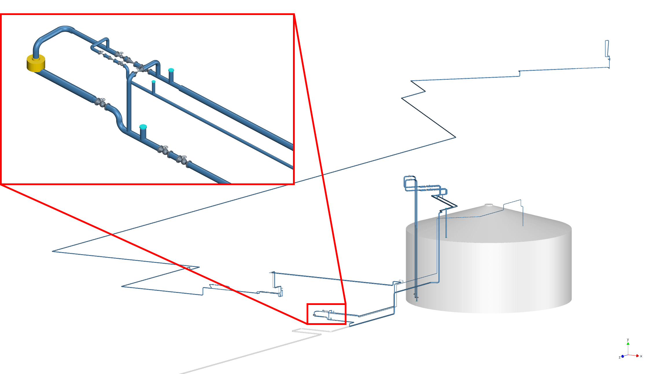
An LNG-plant was planning to construct an additional LNG bunkering line that will be used to fuel ferry ships in Stavanger. Both a main and booster pump are used to achieve the flow through the 600-meter-long pipe line connecting to the ships through a loading arm, which included an emergency shutdown valve. During operation of the bunkering line upset conditions such as pump trip or fast valve operations may cause excessive loading of the bunkering line. Dynaflow Research Group (DRG) was taken on to evaluate several worst-case scenarios that lead to pressure surges in the new LNG bunkering line. Different solutions are explored and presented to reduce surge pressures in the line. Additionally, unbalanced forces are calculated and supplied to the client for a dynamic stress analysis to minimize the risk for damage to the vacuum insulated piping.
Assessment
In the pressure surge analysis, four main scenarios were evaluated:
- A pump trip of the booster pump
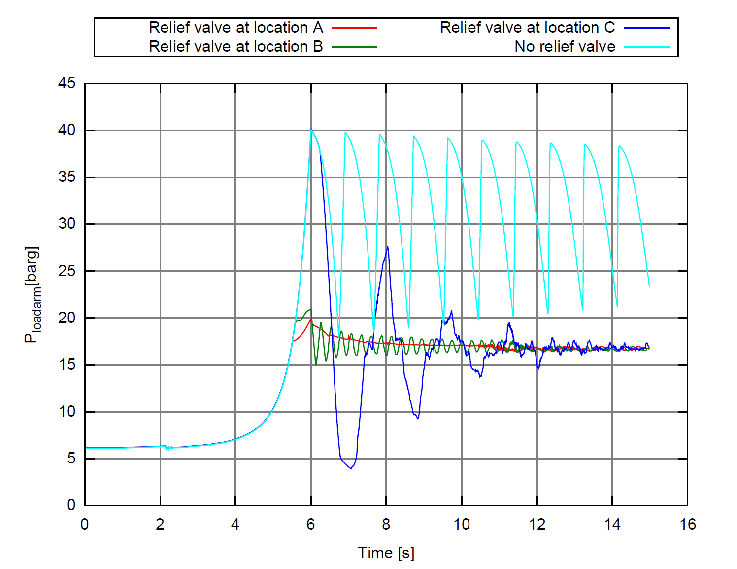
- Rapid closure (5s) of the emergency shutdown valve on the loading arm while the booster pump maintains power
- Rapid closure (5s) of the emergency shutdown valve on the loading arm with simultaneous shutdown of the booster pump
- The water hammer effect from initiating flow in an empty LNG loading arm
To reduce high surge pressures, caused by the closure of the emergency shutdown valve, the application of pressure relief valves was taken into account. Therefore, the valve settings and locations were varied in close discussion with the client. Secondly, the closure profile of the emergency shutdown valve was analysed in order to provide a solution in which no costly additions to the system were necessary. In case of a pump trip, the presence of cavitation in the system was analysed and found not to be an issue. Several recommendations were made to reduce pressure peaks due to a water hammer effect in the LNG arm during start-up conditions.
Conclusions
The analysis showed that throttling of the main valve needs to be very precise to control the start-up. Alternatively, the use of a cool-down line for the start-up should be considered. Additional pressure relief valves are able to keep the surge pressure peaks within allowables, for which the relief valve backpressure may be no higher than 3 barg.
For the case where the pump is properly shut down during the closure of the emergency valve, the surge pressure stays well within the allowable values without additional precautions.
Several recommendations were made for the emergency valve. The emergency shutdown procedure requires that a valve is chosen with an “equal percentage” closure curve to reduce the surge pressures. Depending on the characteristics of the specific emergency valve it may have a considerable pressure drop. Because the steady-state operation pressure of the system is set to 14 barg, in conjunction with the valves pressure drop, the valve may limit the maximum flow rate supplied to the transport line.