
A third-party review of the HP discharge line at a gas compression station found that the designer’s stress report shows the discharge nozzle conforming to the vendor’s allowable values with the springs pinned, as API 686 requires. At the 7th April alignment check the flange separation exceeded the 4.5mm vendor limit by 2.7mm, and the five other compressor line models re-run in CAESAR II showed no significant discrepancies that could impact the nozzle loads.
HP Discharge Line Flange Misalignment and Broken Tack Welds During Construction
At a gas compression station being assembled in a fabrication yard, the piping connecting to the discharge nozzle of the high-pressure (HP) compressor did not align within the limits set by the compressor supplier. The station has three compressor stages, with the piping designed by one party and the compressor supplied by another.
At the first alignment check, the four spring supports in the HP discharge line were locked in their cold position for alignment, and the pins were then removed to verify flange alignment, as the vendor procedure required. The pipe rose on the unpinned springs. No gap measurement was taken. Verbal estimates of 30mm between the flange blades, less 6.35mm for each raised face, give approximately 17mm between the flange faces, against a vendor maximum of 4.5mm before bolting (3mm gasket thickness with a tolerance of +/-1.5mm).
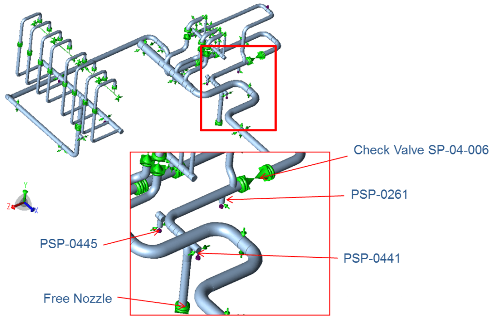
The inspection that followed found four of the eight tack welds temporarily securing hold-down support PSP-0262 broken, which suggested that there might be a more significant engineering problem. The design temperature range of -29°C to 190°C and the associated thermal expansion made it difficult to keep the discharge nozzle loads within the allowable values of 5xNEMA or 2.7xAPI 617.
Reconciling API 686 with the Compressor Vendor's Connection Procedure
API 686, paragraph 4.5.6 of Chapter 6, requires the piping engineering design inspector to verify, before alignment checks proceed, that the springs are locked at the cold load setting. The vendor procedure releases the elastic supports by removing the locking pins once flange tolerances are checked, requires the pipes to remain in position, and allows the pins to be reinserted before the flanges are connected.
It states that either condition can give false positive results: free springs could absorb undue stress and be unable to withstand the thermal, pressure and dynamic movements in operation, while pinned springs could make the system rigid so that undue stress goes unnoticed until final release. Here the pipe rose by 10mm or more when the pins were removed, so the requirement to remain in position was not met.
The reviewer concluded that alignment should be conducted with the springs pinned, as API 686 requires. The designer’s calculation covers the stresses in the nozzle during installation with pinned springs, and the stress report shows the discharge nozzle conforming to the vendor’s allowable values in that configuration. The reviewer therefore found that no undue stress, meaning stress not calculated or foreseen in the analysis, would arise in the nozzle.
Alignment with unpinned springs would reduce the nozzle loads in the sustained (weight and pressure) case, but it would decrease the spring travel available for thermal expansion at maximum design temperature. That would increase the load on the discharge nozzle and could result in the 2.7xAPI 617 limit being exceeded. Reducing the nozzle loads, should unpinned alignment be chosen, is likely to require re-routing of the piping or new spring supports, which are not preferred options at this stage of construction.
Independent Review of Six Compressor Line Models and Spring Supports
The reviewer began with the HP discharge line and reconstructed the sequence of events from discussions with the designer’s piping engineers and the client’s engineers at the yard. The scope was then extended to the other five lines (the suction and discharge lines of the two low-pressure (LP) compressors and the suction line of the HP compressor), with the review focused on the piping that influences the compressor nozzle loads and on the spring supports. The designer’s HP discharge model was reviewed and no evidence of an error was found.
The other five models were re-run in CAESAR II and compared with the marked-up isometric drawings, with no differences seen. For the three suction lines, the routing, operating and design conditions, pipe specifications, materials, restraints and equipment weights were checked, and the calculated stresses and restraint loads matched the issued reports. The LP2 discharge line stresses and restraints also matched.
In the LP1 discharge line, the stress report had been produced with a mistake in a spring support; the model was updated, the report was not, and the recalculated stresses differed from the report by 1 to 3MPa.
The nozzle loads of the LP1 and LP2 compressors and the HP suction nozzle were checked against the API 617 sheets for the hot and cold design cases. The flanges in the five models had been assessed to ASME III NC-3658.3, a method the client had confirmed by email as acceptable.
The spring supports were compared with the manufacturer certificates, the models and the site inspection. The spring rates in the models matched the certificates for every support compared except the constant-effort support PSP-0479B. For the HP discharge line the preset loads also matched, and photographs from the site visit on 9th April showed the springs in the cold (preset) position, within +/-1mm.
Diagnosing the Broken Tack Welds and Excessive Spring Travel
Three possible causes of the broken tack welds at PSP-0262 were tested in the designer’s model: vertical misalignment of the supports near the compressor, insufficient support in the downstream piping, and the transient when the locking pins are removed. Insufficient downstream support gave no vertical lifting force at PSP-0262, with the springs free or pinned.
Vertical misalignment was tested in five cases (up to 5mm at PSP-0261 and PSP-0259, up to 10mm at PSP-0262, and one case without misalignment). With unpinned springs, none produced a lift-off force at PSP-0262. With pinned springs, two produced lift-off forces, of 6.0kN and 8.9kN; the 8.9kN case had a 10mm offset at PSP-0262, and the force would have occurred before the pins were released.
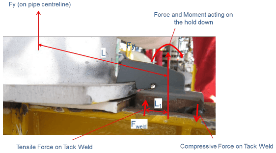
For the pin-release transient, a dynamic load factor of 2.0 (the worst case for a single-degree-of-freedom system) combined with a 10mm offset at PSP-0262 gave a vertical force of 1.3kN at the support. This corresponds to a maximum tensile force of 3.8kN at a tack weld, against an allowable of 3.0kN, and depends on three potentially conservative assumptions: the dynamic load factor, the 10mm offset, and one hold-down support taking all of the vertical load.
The results suggested that a vertical force sufficient to break a tack weld could be generated only under extremely conservative scenarios, and only large misalignment of the supports could produce such a force.
Discussion at the yard raised a further explanation. During installation, the pipe is typically hung at the correct height and the pinned spring supports are placed beneath it, and the spring support box has to pass over stud bolts approximately 10mm long. The client’s engineers at the yard suspected that the pipe was raised to allow this, and that this produced a vertical force at PSP-0262 that broke the tack weld.
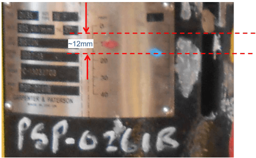
The second anomaly was spring support PSP-0261, which travelled approximately 12mm from the cold stop position when unpinned during the second alignment check on 27th March, against 6.2mm calculated for the same condition. The measurement was inferred from photographs, with a tolerance of about 1mm, taken with the added weights simulating the insulation still present.
Three candidate causes were examined: a 50% reduction in spring stiffness, vertical misalignment of the supports near the nozzle, and incorrect system weight, including the insulation weights added only upstream of the check valve. Across the cases modelled, the travel at PSP-0261 ranged from 6.6 to 8.3mm and never reproduced the measured value. Reduced spring stiffness and weight differences did not appear to be the cause. Vertical misalignment of the supports could be a contributing factor, but no conclusive cause was found.
Alignment, Nozzle Load, Spring and Restraint Review Outcomes
At the third alignment check on 7th April, after realignment and with the springs pinned in the cold position, the separation between the flange faces before bolting was 4.3 to 5.2mm, or 6.3 to 7.2mm with the 2mm of shortening still to occur during welding. Against the vendor limit of 4.5mm, the upper value including the shortening exceeds it by 2.7mm. Yard personnel informed the reviewer that the pipe could be lowered within acceptable limits by adjusting the alignment downstream of the nozzle, and the reviewer understands that the check on 22nd April confirmed flange face alignment. No significant discrepancies that could impact the nozzle loads were apparent in the six analyses.
The on-site presets of PSP-0394B and PSP-0393A should be adjusted: PSP-0394B appeared still pinned at its old preset position, and the preset of PSP-0393A is to be reduced as per the manufacturer’s instructions.
For the hot design case, the compressor nozzle displacements at operating temperature had been used, on the designer’s reasoning that the compressor does not reach the maximum design temperature (for the LP1 discharge nozzle, 115°C operating against 190°C design). The reviewer recommended that the client confirm this assumption, as the reviewer’s practice is to use design values for a design load case.
The API 617 sheet for the LP2 suction nozzle should be updated with the model values, as the hot design loads in the sheet are 10 to 20% larger than in the model and are suspected to be conservative. The pinned positions of the springs in the LP2 discharge line and of PSP-0440D, the construction of six restraints, and the gap at a seventh restraint were also listed for checking. The gaps on all restraints had not been checked during the inspection on 30th April.
Open Questions on the Tack Welds and PSP-0261 Travel
The exact cause of the broken tack welds could not be established with the information available, and the alignment of the supports at the time could not be re-checked because the line has been realigned a number of times since the first alignment check. The tack weld break is suspected to have occurred during installation, as set out above.
The cause of the excess travel at PSP-0261 remains unresolved; determining it would need a further alignment check with the pins out and the HP discharge nozzle unbolted. After discussion with the client, no further alignment check with the springs unpinned will be made, as there is no reason to suspect a fault in the support or in the designer’s engineering. Travel of PSP-0261 above the hot operating marker is not expected to bring the spring to its maximum range in operation.
Frequently Asked Questions
Should spring supports be pinned or unpinned during flange alignment of compressor piping?
In this review, the reviewer concluded that alignment should be conducted with the springs pinned. API 686 requires the springs to be locked at the cold load setting before alignment checks proceed, and the designer’s stress report shows the discharge nozzle conforming to the vendor’s allowable values in that configuration. Unpinned alignment would decrease the spring travel available for thermal expansion at maximum design temperature, which would increase the nozzle load and could result in the 2.7xAPI 617 limit being exceeded.
What can break the tack welds on a spring support hold-down when the pins are removed?
Three causes were tested in the designer’s model: vertical misalignment of the supports, insufficient downstream support, and the pin-release transient. Only a dynamic load factor of 2.0 combined with a 10mm offset at the support gave a tack weld tensile force (3.8kN) above the 3.0kN allowable, and that case depends on three potentially conservative assumptions. The yard engineers suspected that the pipe was raised during installation so that the spring support box could pass over stud bolts approximately 10mm long. The exact cause could not be established.
What flange separation does a compressor vendor allow before bolting the discharge piping?
In this case the vendor maximum was 4.5mm before bolting: a 3mm gasket thickness with a tolerance of +/-1.5mm. At the third alignment check on 7th April, with the springs pinned in the cold position, the separation was 4.3 to 5.2mm, or 6.3 to 7.2mm with the 2mm of shortening still to occur during welding. The upper value exceeds the limit by 2.7mm.