
A new unit was added to an existing gas complex, and the firewater ring main was extended to serve it. Three sets of four 3-inch hydrant valves were modelled, twelve hydrants in total. Each hydrant is required to produce a minimum of 1452 l/min at 7.0 barg, and the hydrant capacities used in the model range from 105.5 to 106.2 m³/h. The installed pipe is EST 20, helically wound at a 55 degree winding angle, with a long-term performance of 20 barg and an allowable short-term overpressure (occasional load) of 26.6 barg. The buried lines were assumed to be full vacuum resistant.
The objectives of the analysis were to define maximum and minimum pressures and flow rates in steady state and in a number of upset scenarios, and to define the measures needed to protect the network against overpressure or vacuum beyond the pipe allowables. The report presents the two most critical upset cases. The first is start-up of a main firewater pump after a fire alarm, when hydrants open and ring pressure falls before the main pump restores supply. The second is closure of the hydrants after the firewater system has delivered its service.
BOSfluids Surge Model Built from CAESAR II Geometry
The layout was first modelled in CAESAR II from the unit plot plan and the overall fire and safety equipment layout, the second of which defined the connection between the pump area and the new unit. This connection comprises part of the existing ring only. The model was then imported into BOSfluids, where the surge elements were included: the main and jockey pumps with their curves, the check valves at the pump discharges and the hydrant valves.
The main firewater pumps P-101A (electric motor) and P-101B (diesel driver) are single-stage centrifugal pumps running at 1470 rpm, with a pump set inertia of 3.3 kgm², a conservative estimate at the lower end. The jockey pump P-102 runs at 2900 rpm with an inertia of 0.3 kgm², also a conservative estimate at the lower end. The discharge check valves are line size (ID 250 and ID 50), with a discharge coefficient of 0.9 and linear closure. The fluid is filtered well water, with a density of 1000 kg/m³ (conservative) and a bulk modulus of 2.2 x 10⁹ N/m². A GRE absolute roughness of 0.05 mm was applied.
The steady state was analysed first to verify the model and to check flow rates and pressure drops. For each area, a steady state with all hydrants of that area open and the main pump running was used to determine the friction loss across the hydrant valves. The resulting hydrant flow rates conform to the values from an earlier stage of the firewater system design. Each upset case starts from its own steady state: the ring pressurised by the jockey pump at minimum flow for start-up, and a steady supply to the open hydrants from one running main pump for closure.
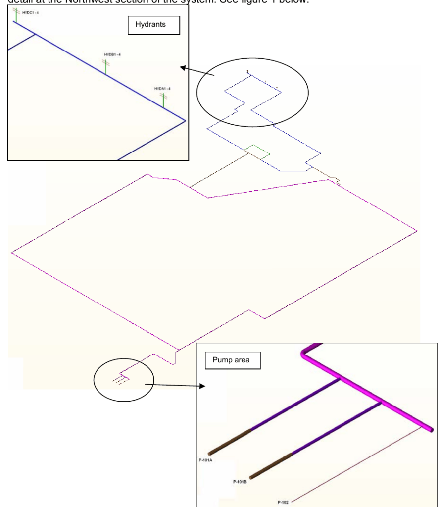
Pump Start-up and Hydrant Closure Load Cases
In the start-up case, the jockey pump P-102 holds the ring at 7 barg and supplies demands up to 11 m³/h. At t = 0 s the three sets of four hydrants start to open. At t = 2.78 s the pressure after the pump manifold drops below 2.70 barg, the setpoint at which a main pump starts, and P-101A is started over an assumed 5 seconds. If the pressure is not restored above 10.0 barg within 30 seconds, the control logic starts the second main pump.
In the closure case, P-101A is running and the jockey pump runs against its discharge check valve, which the manifold pressure from the main pump holds closed. At t = 0 s all twelve hydrants start to close simultaneously at 1 second per inch of diameter, a total closure time of 3 seconds. An additional analysis applied a 0.5 second interval between successive hydrant closures at the same rate, which extends the total closure time to 8.5 seconds.
Hydrant Closure and Pump Start-up Results
With simultaneous closure over 3 seconds, the maximum pressure, near node 740, exceeded the 26.6 barg short-term allowable. The report identifies as a possible solution the prevention of simultaneous or near-simultaneous closure and the extension of the total closure period. With the 0.5 second interval, the maximum pressure was 20.3 barg at node 765, the branch to hydrants HYDC1 to HYDC4, within the 26.6 barg allowable. The report also states that if the closure time of each hydrant is based on 1⅓ seconds per inch of line size, the peak pressures stay within allowable limits.
In the start-up case the pressure fell below atmospheric, reaching its minimum at an elbow at node 510. This is acceptable on the assumption that the buried lines are full vacuum resistant. Within 30 seconds the maximum pressure reached 13.31 barg at node 250, downstream of the jockey pump check valve, and the report records that the maximum pressure after main pump start stays within acceptable levels. After about 20 seconds a steady pressure of 12.1 barg was reached at node 350, after the pump manifold. As this is above 10.0 barg, start of a second main pump is not required in this case. The maximum velocity of 7.78 m/s, at node 30 during pump start-up, is acceptable.
| Case | Total time | Peak pressure | Location | Against allowable |
|---|---|---|---|---|
| Simultaneous hydrant closure, 1 s/inch | 3 s | Exceeds 26.6 barg | Near node 740 | Exceeds |
| Hydrant closure at 0.5 s intervals, 1 s/inch | 8.5 s | 20.3 barg | Node 765 | Within |
| Main pump start-up | Steady after about 20 s | 13.31 barg | Node 250 | Within acceptable levels |
Hydrant Closure Timing and the GRP Occasional-Load Allowable
The report concludes that the results for the transient cases stay within the allowable figures for the applicable piping if valve closure rates are limited and simultaneous hydrant closures are avoided. It recommends that the closure of the open hydrants be distributed over a time interval and that the interval between closures be prevented from dropping below 0.5 seconds. As an alternative, the closure time of each hydrant could be stretched beyond 1 second per inch of line size.
Both closure analyses used the same rate of 1 second per inch for each hydrant. Simultaneous closure over 3 seconds exceeded the allowable. Closure at 0.5 second intervals over 8.5 seconds gave 20.3 barg. Both peaks were assessed against the 26.6 barg occasional-load allowable.
Questions on Firewater Surge in GRP Piping
How fast can firewater hydrants close without overpressuring GRP pipe?
In this analysis, closing the hydrants at 1 second per inch with a 0.5 second interval between closures held the peak to 20.3 barg, within the 26.6 barg short-term allowable. The report also states that a closure time of 1⅓ seconds per inch of line size keeps peak pressures within allowable limits.
What are the pressure limits for EST 20 GRP firewater pipe?
The installed EST 20 pipe has a long-term performance of 20 barg and an allowable short-term overpressure (occasional load) of 26.6 barg.
Does a buried GRP firewater main see vacuum during fire pump start-up?
Yes. During hydrant opening and before the main pump start, the pressure fell below atmospheric at an elbow. This is acceptable on the assumption that the buried lines are full vacuum resistant.