
This project covered a family of glass fibre reinforced plastic (GRP) couplers, designated FWC, in five configurations: a DN600 coupler in a small (S) and a medium (M) variant, a DN1200 medium coupler, a DN2400 large coupler, and a DN3600 extra large coupler. Each coupler is a long cylindrical GRP sleeve lined with an EPDM gasket containing four individual lips that provide the pressure seal. The couplers are non-tensile resistant, which means they are not designed to transfer the axial thrust generated by internal pressure. They are designed for maximum long term pressures of 32 Barg for the DN600 configurations, 16 Barg for the DN1200, and 10 Barg for the DN2400 and DN3600. The pipes joined within them are centrifugally cast, non-tensile resistant GRP pipes with reinforced wall thicknesses of 19.3 mm (DN600), 20 mm (DN1200), 57 mm (DN2400) and 62 mm (DN3600).
The purpose of the work was to calculate the stresses and strains in each coupler and in the inserted pipes, to assess those values against an allowable stress envelope, and to give recommendations for improvement of the joint on the basis of the calculated stresses and strains.
Axisymmetric Model of the Coupler, Pipe and Gasket
A finite element model was prepared for each coupler configuration. The inner pipe was approximated locally as a conical converging and diverging shape. This captured the two extreme contact situations between the inner pipe and the coupler within a two-dimensional rotational model. This approach disregards three-dimensional effects such as ovalisation of the coupler and inner pipe, which were instead assessed separately. Because eliminating ovalisation over-estimates the hoop stresses, the approach was believed to be conservative.
The model included the GRP coupler, the GRP inner pipe, and the EPDM Shore A 60 rubber gasket. The gasket was modelled with a large displacement formulation and a Mooney-Rivlin material model. Contact surfaces were defined only between the inner pipe and the rubber gasket. No contact was assumed between the fibreglass of the coupler and the inner pipe.

Two Calculation Steps and Three Load Cases
The analysis was run in two steps. In the first step, the GRP inner pipe, initially modelled at a smaller diameter, was radially expanded to its correct diameter. This step simulated installation of the joint and seating of the gasket. In the second step, internal pressure was applied.
Three load cases were assessed for each coupler:
- Case 1, the nominal case: the pipes are inserted with coinciding centrelines and the system is then pressurised.
- Case 2: one pipe end is mitred and inserted with a correspondingly deflected centreline, with the rotation at the top side of the coupler, before pressurisation.
- Case 3: as Case 2, with the rotation at the bottom side of the coupler.
The mitre angle was 3 degrees for the DN600 and DN1200 couplers and 1 degree for the DN2400 and DN3600 couplers.
For the DN600, DN2400 and DN3600 couplers, the compression in the first (small) seal lips was insufficient to contain the pressure. The pressure was therefore assumed to be contained between the second seal lips on both sides for all load cases. The pressure-induced stresses were found to be nearly independent of the mitre and centreline deflection angle across the range considered. The stresses in the coupler are mainly dominated by axial bending caused by internal pressure acting on part of the internal surface.
Tsai-Wu Design Envelope and Ovalisation Stresses
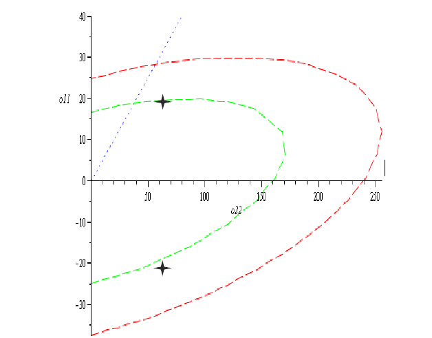
No bi-directional test data were available for the coupler. Its bi-directional behaviour was therefore estimated using the Tsai-Wu failure criterion, an interactive stress-based criterion for composites, with estimated compressive strengths and an estimated interaction coefficient f* of -0.5. Long term uni-directional strengths of 25 MPa axial and 240 MPa hoop were derived from short term values of 50 MPa and 480 MPa by applying a factor of 2, assuming an operating temperature below 30°C. A safety factor of 0.67 was applied for internal pressure to obtain the design envelope used for every stress check. The pipe envelopes were based on the long term pipe strengths and conservatively used the uni-axial allowable under bi-axial loading.
Ovalisation was treated as a distinct contribution, and three conditions were reviewed:
- Condition A: ovalisation of the coupler and inner pipe from the varying gasket contact pressure when the mitred pipe is installed.
- Condition B: ovalisation of the inner pipe and coupler from the radial pressure unbalance in operation.
- Condition C: rotation of the inner pipe inside the coupler from the moment created by that unbalance.
The resulting hoop bending stresses were added to the coupler pressure hoop stress in the assessment. The added values were 1 MPa for the DN3600 and up to 9.5 MPa for the DN600 medium coupler.
Results Against the Design Envelope
When the stress states were plotted onto the design envelope, the stresses in four couplers stayed within the allowable stress design envelope: the DN600 small and medium, the DN1200 and the DN3600. Pipe stresses stayed well within allowable values for all pipe sizes considered.
For the DN2400 coupler, the operating stresses were on the edge of the design envelope. In the nominal case they reached +19 MPa and -18 MPa axial and approximately 65 MPa hoop. A small change in axial bending stress could therefore cause the stresses to exceed the envelope.
An additional load case was defined in which the pressure seal is achieved by the inner gasket lips. Because the stresses are independent of the mitre angle, this case was assessed for the nominal case with operational loads only. The hoop stress was approximately 58 MPa and the axial bending stresses were +19.4 MPa and -21.2 MPa. The stresses exceeded the design envelope due to the increased axial bending stresses. A pressure-length sensitivity study was then carried out to investigate the effect of the length over which the pressure acts, so that the stresses would not exceed the design envelope in case of manufacturing scatter.
Additional Laminate for the DN2400 Coupler
The sensitivity study concluded that 2 mm of additional laminate, corresponding to five additional plies, was required for the DN2400 coupler. The nominal case was then re-analysed with the added laminate. The operating stresses were +15.1 MPa and -15.6 MPa axial and approximately 54.5 MPa hoop.
The ovalisation stresses due to installation may be significant depending on the angle of the mitred pipe. Taking a design margin into account, mitre angles larger than those specified were not recommended.
Recommendations
Contact between the GRP part of the coupler and the pipe outside diameter was identified as a critical aspect. When pipe deflection increases until these GRP parts make contact, the axial (longitudinal) bending stresses in the coupler show a sharp increase. To avoid contact, the analysis highly recommended tapering the inside edges of the coupler, preferably with the rubber gasket extended towards the tapered outer edges of the joint.