
A seawater dump caisson made of glass-reinforced epoxy (GRE) needed its wall, laminate and joint details defined. The task was to find thicknesses and bonding lengths that would keep stresses within the allowable stress envelope conforming to ISO 14692, and to determine the loads that the restraints, flanges, laminated joints and temporary supports would have to carry.
The Caisson and Its Loads
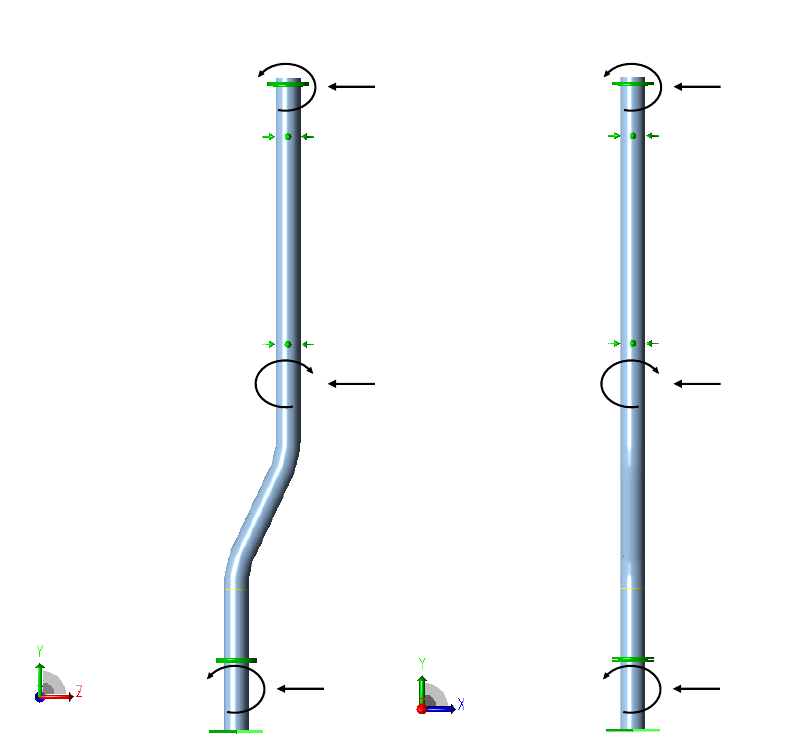
The caisson is a vertical 42-inch unit, 27.4 m long with a 1,000 mm inner diameter. A 25-degree offset section shifts the line sideways by 2,175 mm. Five nozzles connect to it: four oblique nozzles on the cylindrical body, N1 to N4, and one, N5, in the blind flange at the top. The caisson is built from five spools, joined partly by flanges and partly by lamination joints, and is anchored at its bottom flange where it meets the carbon steel section below. Two guide supports hold it laterally.
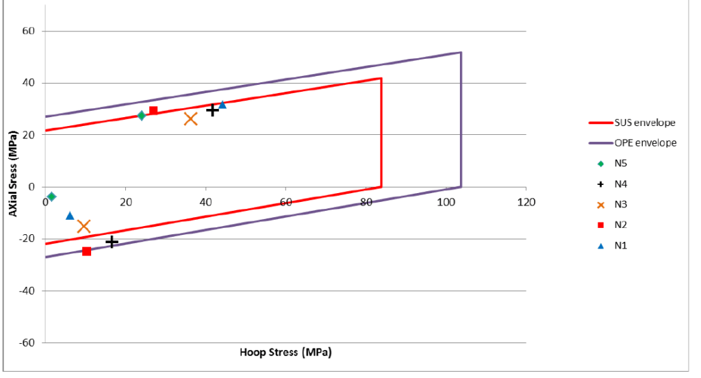
The caisson must withstand both internal pressure and vacuum. The design pressure ranges from 3.5 Barg internal to minus 0.7 Barg, which is equivalent to an external pressure of 0.7 Barg. The design temperature ranges from minus 7°C to 50°C, and each nozzle carries external forces and moments specified by the supplier. The material, GRE of the CST series with a 55° winding angle, has a qualified stress of 125 MPa. With part factors conforming to ISO 14692-3, this gives operational allowables of 104 MPa in hoop stress and 27.0 MPa in axial stress.
Two Models, Two Scales
The assessment was split into two parts. The first looked closely at each nozzle; the second looked at the caisson as a whole.
The starting point was the header wall. Its thickness was determined from the vacuum requirement, using the ISO 14692 external-pressure equation with a safety factor of 1.5 as discussed with the client. This gave a 15 mm wall.
Each nozzle and its intersection with the header was then modelled on its own in FE Pipe, since stresses from interaction between neighbouring nozzles were determined to be minimal. Every nozzle was checked for combinations of maximum and minimum in-plane and out-of-plane bending moment, and for all five the critical combination was maximum in-plane with minimum out-of-plane moment. Wall and laminate thicknesses were selected for that case.
Three nozzles needed particular attention. At N1, whose diameter is relatively large compared with the header, the laminate was wrapped around the full header circumference rather than applied as a local pad. At N4 a local pad was tried first, but it led to high stresses in the header at the laminate interface, so a full-circumference laminate was used there too. At N5, in the top blind flange, the more critical factor was rotation of the plate edge under internal pressure rather than stress. An initial investigation showed that keeping the rotation below 0.5 degrees needed more than 80 mm of thickness, and an 85 mm flange was chosen because it compares to the supplier’s standard 12.5 bar blind flange.
For the caisson as a whole, a beam model was built in CAESAR II. Five operational load cases were run, each arranged to maximise the load on a different part of the system: the anchor and flange without guides, the anchor and flange with guides, each of the two guides in turn, and the 25-degree offset, which preliminary analysis had identified as the location of highest stress. A separate model covered transport and installation, when the upper four spools rest on two temporary supports under their own weight alone.
What the Analysis Showed
All five nozzles came out inside the ISO 14692-3 operational stress envelope for their critical load case.
Across the header, the 15 mm wall kept stresses within the allowable envelope for all load cases. The highest stress occurred where preliminary analysis had pointed: the upper bend of the offset, under load case 5. A laminate at least 20 mm thick is needed there, and with it the stress is 26.6 MPa, 77.3 percent of the local allowable stress according to ISO 14692.
For convenience, each combination of axial force and bending moment was converted into an equivalent pressure and added to the 3.5 bar design pressure. The bottom flange came out at 14.7 bar, a PN16 rating, and the spool 2 to spool 3 flange at 7.9 bar, a PN8 rating. The top flange of spool 5 came out at only 4.1 bar, but a PN12.5 flange was recommended there to match the blind flange above it and create a balanced system. An 8 bar flange would also work if its bolt profile matches the blind flange.
The five laminated joints, comprising the cut in spool 2, the spool 3-4 and spool 4-5 joints and the two offset bends, were checked for average shear stress against a 1 MPa limit. With no lengths specified, 250 mm either side of each straight joint and 510 mm either side of each bend were assumed. Four joints came in at 0.90 MPa or below. The spool 3-4 joint was the tightest: the space between it and the N3 laminate allowed only 189 mm, and this should be increased to 200 mm, which brings the shear stress to 0.96 MPa.
During transport and installation, the highest load on a temporary support was 28.6 kN, vertical at the upper support, within the allowable forces specified for those supports.
After an earlier final issue of the assessment, the geometry of nozzle N3 was revised, with its loads unchanged. Its laminate was updated, and the effect on laminate, restraint and flange loads was negligible. The revised drawing also allowed the N3 intersection to sit up to 600 mm lower. That too had a negligible effect on loads, although the N3 header laminate would then need to be extended and would overlap the spool joint laminate, which the supplier confirmed is possible.
Lessons from the Assessment
- First, the header wall thickness was set by the 0.7 Barg vacuum condition, and the resulting 15 mm wall kept header stresses within the allowable envelope for all load cases, with at least 20 mm of laminate required at the upper offset bend.
- Second, laminate layout was decided nozzle by nozzle: a full-circumference laminate was used at N1 because of its relatively large diameter and at N4 because a local pad led to high stresses in the header at the laminate interface.
- Third, expressing flange loads as total pressures gave PN16 and PN8 ratings for the lower two flanges, while at the top of spool 5 a PN12.5 flange was recommended to match the blind flange, although the calculated pressure there was 4.1 bar.