
The Firewater Network
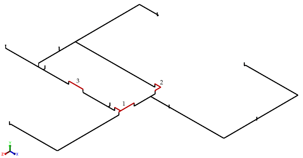
The firewater network in this case is built from glass-fibre reinforced epoxy (GRE), grade Wavistrong EST 20, with DN150 pipe running mainly underground. Above ground, steel sections connect to the GRE by flanges, and vertical branches rise to fire hydrants and similar connections. The system was specified for a design pressure of 16 barg at 65 °C, with a hydrostatic test pressure of 24 barg.
Overstressed Elbows and Tees in the Original Design
A static stress analysis to ISO 14692 showed that the original design needed modification. In the operational load case, the most critical of the three analysed, stresses at a number of elbows and tees exceeded the allowable, the highest reaching 137 percent of allowable at a tee. In the hydrostatic test case the highest value was 101 percent. The original drawings also showed a buried thrust block beneath the hydrant connection.
The CAESAR II Model and Acceptance Criteria
The network was modelled in CAESAR II under three load cases, each including the weight of the water-filled pipe: sustained at 16 barg, operational at 16 barg and 65 °C, and hydrostatic test at 24 barg. The steel sections were included only to provide adequate boundary conditions for the GRE, and their stresses were not assessed.
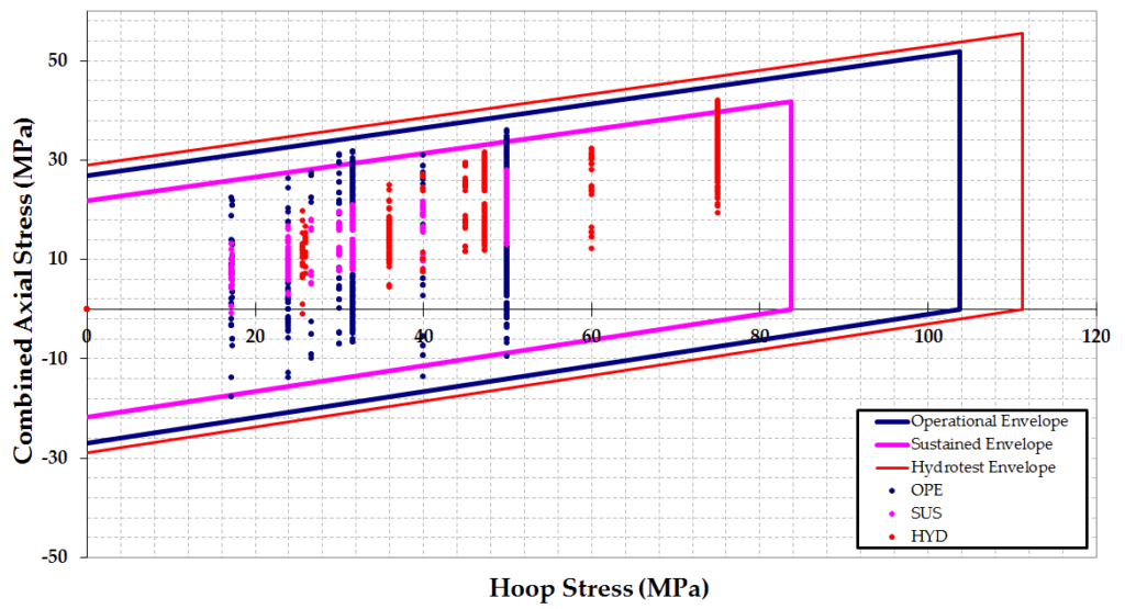
The stress at every node was plotted against the ISO 14692 stress envelope, which combines axial and hoop stress; a point inside the envelope is acceptable. Flange loads were converted to an equivalent pressure and checked against the pipe supplier’s allowable of 33.2 bar for the operational case, which is twice the PN20 pressure rating multiplied by a safety factor of 0.83.
Changes to the Design
Stress was reduced by wrapping the pipe in flexible material to reduce soil load wherever possible, and by adding wall thickness only where needed. K-flex is proposed as the wrapping, preferred over polystyrene provided its elastic modulus is below 0.05 MPa. Modifications were specified at 17 locations: 13 elbows, two tees and two vertical GRE-to-steel transitions. Thirteen received wrapping alone, and four received local wall thickness increases to between 3 and 7 mm, with the most highly stressed tee increased to 7 mm.
The report also requires three further changes. The buried thrust blocks at the hydrant branches are to be removed. The hydrant flange connections are to be anchored to a rigid support structure and not solely to the pipe. And because a conservative gasket sealing circle equal to the pipe inner diameter gave too high an equivalent pressure at some GRE-to-steel flanges, the sealing circle should be at least 170 mm, with heavy-duty flanges fitted where it is smaller.
Support details for the steel sections were not available, so the steel was assumed to be rest-supported. Guides or axial stops in their place may significantly influence the GRE stresses and flange loads.
Stresses and Flange Loads Within Acceptable Limits
With the modifications applied, all stresses fall within the ISO 14692 envelopes for the sustained, operational and hydrostatic load cases. The highest operational stress fell from 137 percent to 93 percent of allowable, and the highest hydrostatic stress from 101 percent to 90 percent. Flange loads are within acceptable levels for all three load cases. The report concludes that, provided the system is built according to the recommendations, it fulfils the requirements of ISO 14692.
What the Assessment Shows
Wrapping to reduce soil load was specified at 16 of the 17 modified locations, while wall thickness was increased at only four.
The verdict is conditional. It depends on a gasket sealing circle of at least 170 mm and on the assumed rest support of the steel sections. Large deviations from that support arrangement, in particular guides or axial stops, may lead to significantly higher stresses and flange loads than reported.