
The main firewater line for a new oil terminal jetty is made from glass reinforced epoxy (GRE) pipe. It starts at the onshore transition between underground and above-ground pipe, where it connects to steel lines, and follows a jetty about 1.5 km long. A firefighting platform about one third of the way along the jetty houses the firewater pumps, which take in seawater from below the jetty. The pumps feed the DN300 shipside piping, which runs towards the berth platforms, and the DN400 landside piping, which runs towards land. A DN150 branch serves a fire hydrant on the landside. Pipe stresses were checked against the 20-year allowable stress envelope of ISO 14692.
Loads and Trestle Movement on the GRE Firewater Line
The line has a design pressure of 19 bar gauge at a design temperature of 60°C and was installed at 20°C. The hydrotest pressure is 28.5 bar gauge. The extreme basic wind velocity is 30 m/s and the operational basic wind velocity is 20 m/s. The horizontal seismic acceleration for the stress analysis is 0.424 g, which includes a seismic acceleration reduction factor of 0.7, and no vertical seismic acceleration is applied. Wave impact and earthquake displace the trestles, and trestle movement contributes to a large extent to the total pipe stress.
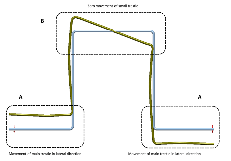
The pipe rests on trestles. Each main trestle is a truss structure 45 m long. The trestles are stiff compared with the GRE piping, so the analysis treats them as rigid bodies that translate and rotate but do not bend. The six trestles between two expansion loops are rigidly connected and move as one structure 270 m long. At each loop, the two adjacent main trestles and the small trestle that supports the outer part of the loop have no direct connection, so each can move relative to the others. The contractor specified zero movement for the small trestles.
Expansion loops accommodate thermal expansion, expansion due to pressure thrust and pipe displacement from trestle movement. The as-received pumping station loops were undersized for accommodating trestle displacement, thermal displacement and earthquake acceleration while keeping the loads on the pumps and the pipe stresses within allowable values.
GRE Stress Analysis in CAESAR II with Paired Displacement Cases
The system was modelled in CAESAR II, with the buried onshore section modelled in the buried piping modeller module. Pressure, temperature, wind, seismic acceleration and trestle displacement were treated as quasi-static loads. Wind loads follow EN 1991-1-4. Stresses were evaluated to ISO 14692, and the stress intensification factors for tees and elbows were computed to the same standard. No partial factors are applied to the loads. The allowable stress values carry partial factors of 1.5 for sustained loads, 1.20 for operational loads and 1.12 for occasional loads.
The analysis comprises 15 load cases: one hydrotest, two sustained, one operational and eleven occasional. Wave displacement cases are combined with wind loads. Two further cases cover displacement of the platform: D8, lateral displacement due to waves, combined with wind, and D9, longitudinal displacement due to seismic action, not combined with wind. Seismic displacement and seismic acceleration are not combined in a single load case, and the seismic acceleration cases include no friction.
The contractor specified the maximum displacement per trestle in the lateral and longitudinal directions. The specification does not state how the trestles move relative to one another. Where all trestles move by the same magnitude there is no differential movement, but between trestles with no direct connection a differential displacement can exist. The displacements were therefore interpreted to give the largest pipe deformation and the highest stresses. Two displacement cases were set up for lateral wave displacement (D1 and D2), two for lateral seismic displacement (D4 and D5) and two for longitudinal seismic displacement (D6 and D7). In each case some trestles have zero displacement and others a non-zero displacement, which gives the largest differential displacements at the critical points. The contractor must verify this interpretation. If a misinterpretation is found and the analysis is not revised, pipe failure is possible.
The fire-resistant coating is included in the model for its weight, its elastic properties and its contribution to pipe bending stiffness. It is conservatively assumed to carry no load, so the basic pipe carries all load.
Modifications to Loops, Pipe Class, Supports and Platform Piping
The pumping station loops were originally routed from the platform directly on the main trestles, where the large trestle displacements could not be accommodated. Both loops were enlarged and now run from the platform to the small trestle next to the platform, as the steel lines do. An extra loop close to the platform was added to both pumping station loops to accommodate platform displacements. Axial stops and guides were added to accommodate seismic and wind loads. On the other offshore loops, a few weight supports were added because otherwise the stress due to weight takes up too large a part of the allowable stress, and one axial stop per loop leg accommodates wind and seismic loads without impairing thermal expansion and trestle displacements too much. PTFE base plates, which allow sliding with low friction, are specified for all supports that are part of the loops.
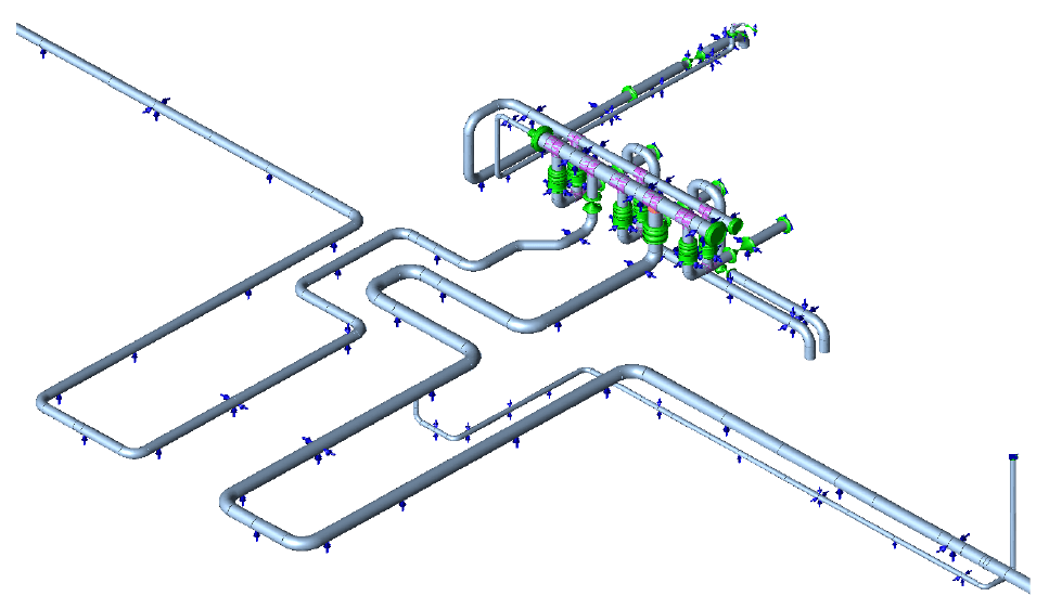
The piping on the trestles and onshore is pipe class EST20. EST25 is applied at the loops and at the 26° bend between trestles 24 and 25 of the landside piping, because additional strength is required there. The platform piping is also EST25. Additional reinforcing laminate is specified at a few locations next to elbows on the loops and at the 26° bend.
At the onshore loop, the pits where the GRE lines connect through a valve to steel lines were shifted by ±0.5 m away from the GRE elbows to create additional flexibility. The DN150 hydrant branch originally connected to the DN400 pipe at a position exposed to large longitudinal displacements of the header pipe from thermal expansion. It now connects to a part of the pumping station loop where the header pipe displacements are lower.
At the platform, each vertical pipe of the DN300 pump branches has a bellows with tie-rods, which prevent a large pressure thrust acting on the pipe supports. The bellows accommodate thermal expansion of the pump branches. A limiter on the steel flange next to each pump nozzle prevents large axial loads on the nozzles.
Verification Against Allowables and Reported Displacements
With the modifications included in the model, all GRE pipe stresses are within the ISO 14692 20-year allowable stress envelope. Each flange was assessed by comparing its equivalent pressure with an allowable equivalent pressure, Pall = 2 × Pclass × f. Pclass is the pressure class of the flange, equal to that of the connecting pipe, and f is the ISO 14692 partial factor: 0.67 for sustained, 0.83 for operational, and 0.89 for occasional and hydrotest load cases. The equivalent pressure is below the allowable pressure for all flanges.
The pump vendor document specifies no maximum allowable moments, so only the force components of the pump nozzle loads were verified against allowable values. The axial component was not checked, because the load from the GRE pipe acts on the axial stop installed at the flange of the pump nozzle. With the modifications implemented, the force components checked are within the allowable values.
Pipe displacements and support loads are reported for a horizontal seismic acceleration of 0.605 g, which omits the 0.7 reduction factor included in the 0.424 g used for stress. The reported displacements are total displacements; the displacement relative to the trestle is the reported value less the imposed trestle displacement. The support loads should be used for sizing the supports. The displacements should be used to check support baseplate length and clashes with the trestle frames and other parts on the trestles. The check for clashes with other piping is outside the scope of this analysis, because it requires the results of the analysis of the steel piping.
Support Assignment and Recorded Assumptions
The report specifies, for each support in or close to a horizontal loop, which trestle it must be installed on. Different displacements apply to different trestles, and a support installed on a different trestle from the one specified causes high stresses. The supports to be built should be checked against this assignment.
The report also records assumptions that need checking. The contractor’s marked-up drawing places the fixed point between trestles 1 and 2, while the pipe manufacturer’s isometrics place the axial stop on trestle 1 next to the T-junction. The contractor’s drawing is assumed to be correct, and the analysis models the fixed point between trestles 1 and 2, with a fixed connection between trestle 1 and the T-junction. At the T-junction, assumptions about the steel continuation line were made because no clear drawings were available, and the contractor should check them. The flange that connects to the fire hydrant is assumed to connect to a structure fixed to trestle 22.
Frequently Asked Questions
Why were the pumping station loops on a GRE firewater line rerouted?
The loops were originally routed directly on the main trestles, where the large trestle displacements could not be accommodated, so they were enlarged and now run to the small trestle.
How are partial factors applied in an ISO 14692 stress check on GRE piping?
No partial factors are applied to the loads; the allowable stress values carry 1.5 for sustained, 1.20 for operational and 1.12 for occasional loads.
What happens if a GRE pipe support is installed on a different trestle from the one analysed?
Different displacements apply to different trestles, so the support causes high stresses.