
Consolidating Gas Flow onto a Single Metered Line
A platform gas metering station has three parallel metering lines, two active and one spare. The modification replaces the orifice-type flow meter in the most eastern line with an ultrasonic (US) flow meter and directs the complete gas flow through that line. Gas velocities in the 10-inch metering pipe increase to values above 20 m/s, giving a maximum stagnation head (ρV²) of 44,000 Pa. This condition does not comply with the line sizing criteria of GS EP ECP 103, and a flow/vibration assessment has to be made.
For gas velocities at this level, with the applicable gas density and pipe size, the gas momentum flux reaches values above 2,000 N. A flow variation of 5%, taken as an example, then gives load variations of the order of 200 N, which may result in pipe vibrations. An earlier vibration risk assessment identified a potential vibration problem when excitation frequencies come close to 14 Hz and/or 28 Hz. At these frequencies locking-in can occur: vortices shed in the metering line excite the acoustic frequencies. The acoustic resonance of the flow inside the pipe can interfere with a natural mechanical frequency of the system, and excessive displacements may occur.
Screening the System Against Flow-Induced Excitation
The assessment compared the flow-induced excitation frequencies of the piping system with the natural mechanical frequencies of the structure. Standard practice is to treat all natural modes with frequencies within 10% of the excitation frequency as likely to be excited. Whether a mode is excited also depends on the direction, magnitude and location of the excitation forces. After the modification, the excitation mechanism of interest is located in the line with the US flow meter. The natural frequencies that result in movement of that line therefore have to be suppressed, and those within 10% of the excitation frequencies in particular have to be shifted.
Support Arrangement and Skid Frame Reinforcement
Guide supports are recommended at nodes 920, 930, 960, 970 and 1000, and axial stops at nodes 800 and 1000, to suppress axial and lateral movement of the metering line. The support at node 1000 combines a guide and an axial stop. All supports have zero clearance except the axial stop at node 800, which has a 5 mm gap to accommodate differential thermal expansion and to reduce excessive static support loads.
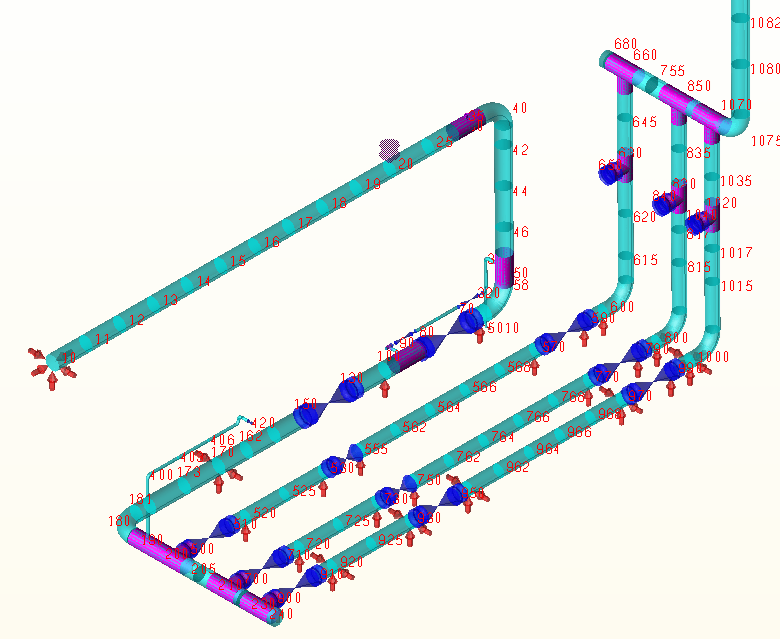
The maximum support loads occur in different operating modes. They are 9 kN lateral at the guides at nodes 920, 930, 960 and 970, 2 kN lateral at the guide at node 1000, 10 kN axial at the stop at node 800 and 30 kN axial at the stop at node 1000. When the supports are installed and the attached steel is sufficiently stiff, the dynamic forces on the supports are of the same order as the 200 N load variation in the flow, so the static loads dominate when the supports are sized. The support modifications were checked for static stresses and comply with the stress demands of the Stoomwezen code.
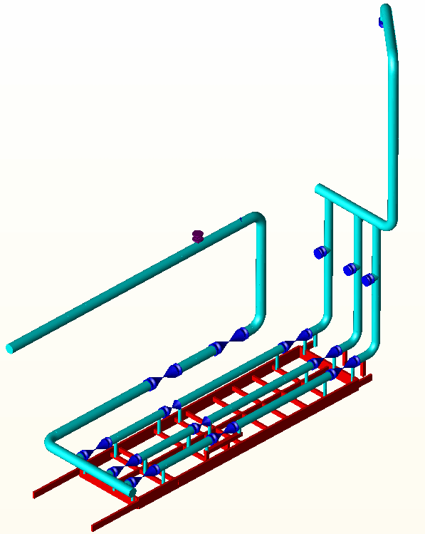
The frequency analysis with the added supports assumed that the steel attached to the supports was a few orders of magnitude stiffer than the piping. On that basis, the first natural frequency at which the US metering line deflects significantly as a beam is 64.3 Hz, far from 14 Hz and 28 Hz. In the unchanged configuration, this movement would already be present from 7 Hz. To determine the influence of the skid frame, the piping model with the changed pipe supports was attached to a steel model representing the skid frame, and the 2-inch vent branches were removed to focus on the movement of the 10-inch metering lines. Preliminary calculations showed that the frame is insufficiently stiff. A number of natural frequencies can cause excessive movement of the metering line, and three of them, at 14.5649, 20.0208 and 29.4974 Hz, were plotted. The lateral and axial movement seen in the plots is mainly caused by insufficient stiffness of the 4-inch dummy supports.
The following changes to the skid frame are recommended. Diagonal tube members of 2-inch size are welded to the dummy supports and the skid frame at nodes 905, 920, 930, 960, 970 and 990. Because the pipe span between nodes 960 and 970 is relatively large, the lateral movement in this part will be largest. The diagonals at nodes 930, 960 and 970 are therefore directed towards the mid metering line, which gives a larger supporting span and a more substantial increase in stiffness. The diagonals at the remaining guide supports are directed towards the skid edge frame. Without adjustment, the diagonal members that support nodes 930 and 970 would rest on 150x75x8 hook elements, which have insufficient stiffness; the loads directed from the diagonal members into them would cause relatively large displacements of the hook members. A number of hook profiles are reinforced with UNP180 elements, and a new HEB180 beam supports the diagonal tube member from node 960. An extra 4-inch Sch. 40 dummy is welded in to support a guide support and the new beam.
Natural Frequencies and Vent Branch Support
With the skid reinforcement, the movement of the US metering line decreases significantly for natural modes between 12 and 32 Hz. A few natural frequencies with observed movement of the US metering line still exist, but these movements are small compared with the initial situation. Larger movements of the metering line occur only for frequencies above 32 Hz, outside the excitation frequency range.
The comparison plots show the normalised displacement at natural frequencies close to the excitation frequencies at which locking-in occurs: 14.5649, 20.0208 and 29.4974 Hz without reinforcement, and 15.6431, 21.4113 and 30.1822 Hz with reinforcement. The improvement is smaller than in the analysis with the attached steel a few orders of magnitude stiffer than the piping, in which the first significant beam-type deflection is at 64.3 Hz.
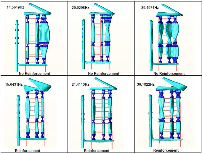
The dynamic runs for the 10-inch metering lines were done without the 2-inch vent branches, mainly because the movement of the vent branches would obscure the dynamics of the metering lines. A separate run with the vent branches installed showed that their displacements are sensitive to the movements of the metering lines. It is recommended to support the vent branches. Dedicated bracing that relieves the tee connections can be used for this purpose, and may be applied if these movements are noticed in the field.
Support Effectiveness and Attached Steel Stiffness
The effectiveness of all supports is determined by the stiffness of the attached steel. A lack of stiffness causes the supports to move with the piping, and low frequency harmonics can then become important again. Calculations of the piping with the skid frame showed that the assumption of attached steel a few orders of magnitude stiffer than the piping is not valid, and that the stiffness of the frame deteriorates the dynamics of the metering line. Reinforcement of the skid frame is therefore needed to guarantee the dynamic improvement.
Frequently Asked Questions
Which natural frequencies of a gas metering line are vulnerable to flow-induced excitation?
Standard practice is to treat all natural modes with frequencies within 10% of the excitation frequency as likely to be excited. Whether a mode is excited also depends on the direction, magnitude and location of the excitation forces. In this case the excitation frequencies of concern were 14 Hz and/or 28 Hz.
Why does skid frame stiffness matter for pipe support vibration control?
The effectiveness of all supports is determined by the stiffness of the attached steel. A lack of stiffness causes the supports to move with the piping, and low frequency harmonics can then become important again. Here, attached steel a few orders of magnitude stiffer than the piping gave a first beam-type mode at 64.3 Hz, but calculations with the skid frame showed it was insufficiently stiff, and it was reinforced.
Why did a 10-inch gas metering line need a flow-induced vibration assessment?
Directing the complete gas flow through one line increases gas velocity in the 10-inch pipe above 20 m/s, giving a maximum stagnation head (ρV²) of 44,000 Pa. This does not comply with the line sizing criteria of GS EP ECP 103. The gas momentum flux reaches values above 2,000 N, and a flow variation of 5%, taken as an example, gives load variations of the order of 200 N.