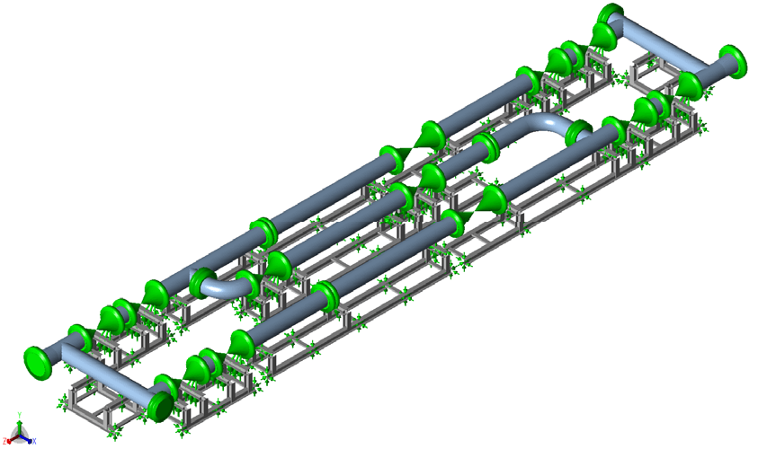
A combined CAESAR II model of a gas metering skid and its structural steel frames was assessed against ASME B31.3 (2006). The piping stresses were below the allowables, the steel stresses were within the allowable limits for the sustained and expansion load cases, and several bolt shear loads exceeded the 32.2 kN allowable for a single 1-inch bolt, so two bolts were taken at those locations.
Gas Metering Skid Layout, Weights and Process Conditions
The skid analysed here carries natural gas through 26-inch, 600# valves and ultrasonic flow meters. The gas can take one of three flow paths, each using one or two flow meters. The flow path is changed by opening and closing the corresponding valves in the skid. The equipment weights used were 5750 kg for a motor operated valve, 5550 kg for a gear operated valve and 1564 kg for an ultrasonic flow meter. The analysis used a design pressure of 88 barg, a design temperature range from -40°C to 82°C, an operating pressure of 71.7 barg and an operating temperature of 37.9°C. The client advised that these pressures have been revised to 87 barg (design) and 70.7 barg (operating). The values used are conservative relative to the revised pressures, so, as agreed with the client, no changes were made to the calculations.
Rigid-Support Bolt Load Estimate and Analysis Scope
Foundation bolt loads had previously been estimated from a piping model in which the steel frame and supporting were assumed to be rigid. The estimated loads were within the 32.2 kN allowable shear load of a 1-inch (25 mm) bolt. The scope was to check the piping stresses against ASME B31.3 (2006), to assess the structural steel against the allowables defined in that code, to modify the structural steel if necessary and to provide bolt loads. Modelling the piping and the structural steel together allowed actual bolt loads to be reported in place of the earlier estimates.
CAESAR II Model Inputs, Load Cases and Modelling Choices
The model was built in CAESAR II. The pipe is seamless steel with a 3 mm corrosion allowance and is insulated with 30 mm of cellular glass. The structural steel is modelled as EN 10025 Gr. S275, with a yield stress of 275 MPa at 20°C. The structural steel specification also permits ASTM A36. The saddles rest on HEB 200 beams. The natural gas was modelled at a density of 90 kg/m³, calculated from the ideal gas law at design conditions. This is conservative relative to the density at operating conditions.
Thirty-eight load cases were analysed: one hydrostatic, six operating, twenty occasional (twelve seismic and eight wind), five sustained and six expansion cases. The hydrotest pressure was 132 barg, 1.5 times the design pressure. Wind loads followed ASCE 7-05, with a basic wind speed of 41 m/s and a drag coefficient of 0.7, and were applied in the North, South, East and West directions. Seismic loads followed UBC 97, with Zone 1 (Z = 0.075), soil profile SB (rock), a seismic coefficient Ca of 0.08, an importance factor of 1.0 and a factor R selected conservatively as 2.2. The maximum seismic load is 0.09W, where W is the weight. The direction of any earthquake was not stated, so the horizontal load was applied in the X and Z directions independently. Horizontal and vertical seismic loads were not applied simultaneously, because the two waves are assumed to have different speeds and so do not arrive together. UBC 97 treats the response as that of a rigid element, so the effect of possible resonance was not considered. The flow path load cases used the worst-case temperature differential for each of the flow paths specified by the client, with the active path at 82°C and the other lines at -40°C, and with design pressure in the active path and 0 barg in the other lines.
The guides were modelled without clearance, which gives conservative lateral loads. In practice a sufficient gap should be included to allow lateral movement of the pipe through the guide. The bolt arrangement on the frames is likely to resist applied moments as a couple, and the stiffness of a bolt to applied moments is orders of magnitude smaller than its resistance to forces. The anchor bolts were therefore modelled as three-way stops, which resist forces and carry no moment, so the moment load is zero on all of the bolts.
Anchor Bolt Shear Loads and the Two-Bolt Arrangement
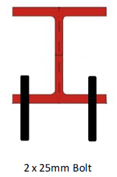
With the structural steel in the model, several bolt shear loads are greater than the 32.2 kN allowable for a single 1-inch bolt. A 2 x 1-inch bolt solution was advised as preferred, with either two bolts on the same side or on opposite sides. At locations where the bolt shear load is above 32.2 kN, the assessment takes two bolts to be used. It is reasonable to assume that two 1-inch bolts in close proximity double the allowable shear load to 64.4 kN.
Pipe Stress, Steel Frame, Anchor Bolt and Nozzle Results
The piping stresses are lower than the ASME B31.3 (2006) allowables, and no modifications are required to the piping layout. CAESAR II does not analyse the structural steel stresses directly. The maximum stress in each section was determined instead from the forces and moments at the nodes of the steel elements. These stresses are within the allowable limits for the sustained and expansion load cases. The frame dimensions were taken from the piping layout drawing. At the client’s request, the saddle design follows a later drawing instead of the one in the piping layout drawing. The structure made of HEB 200 sections is adequate to support the loads. Additional supports were added to two frames so that the piping remains supported if the valves are removed.
The saddle length on top of the HEB 200 beam was reduced to 200 mm. The largest saddle displacement along the pipe axis is 20 mm and occurs only in the unequal temperature load cases; in the other load cases it is less than 10 mm. The 200 mm width of the HEB 200 beam is sufficient to accommodate this displacement.
All bolt shear loads are below the allowable of 32.2 kN for a single bolt or the assumed 64.4 kN where two bolts are used, and all bolt tension loads are below the 60.6 kN allowable.
Nozzle stiffnesses in the lateral and rotational directions were calculated by comparing the loads on the inlet and outlet nozzles if they were fixed anchors with the displacement when the nozzles are free to move. The free-nozzle case is the one analysed, and the stress levels with fixed nozzles do not conform with ASME B31.3 (2006).
Why Bolt Shear Loads Increase When Supports Are Not Rigid
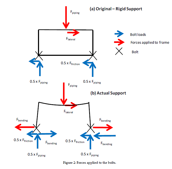
The increase in bolt shear load occurs because the earlier estimate assumed rigid supports, whereas the supports have finite stiffness. For a rigid support, the bolt shear forces equal the lateral force, which is caused by friction, seismic or wind loadings. For an actual support, the vertical load acting on the support bends its upper section, and this bending increases the bolt shear loads compared with a rigid support. This is one factor in the increase; differential thermal expansion between the concrete and the steel frame also has an effect. Crossbeams within the frames are included in the model, but they are not always located directly below the structural steel bridges, as diagram (b) shows. Diagram (b) is included only to illustrate the bending.