A heat exchanger was found to have fluid leakage from the tube side into the shell side after approximately 3 years of operation. Initial inspections suggested that flow-induced vibrations (FIV) were causing support rods to puncture through tube walls. To diagnose and address the source and effects of the FIV inside of the heat exchanger, a detailed dynamic Computational Fluid Dynamics (CFD) investigation was performed.
Methodology and Modeling Approach
Modeling of Tube Deformation
A Caesar II model was used to calculate the stiffness values of the tubes and impingement rods, which were then integrated into the CFD simulations. The model incorporated tube material properties, geometric constraints, and the restraining influence of support rods. However, field inspections revealed that several rods were broken and some were incorrectly arranged, significantly reducing the effective stiffness of the restraint system. This reduction in stiffness increased the susceptibility of the tubes to vibration-induced damage.
Computational Fluid Dynamics Simulations
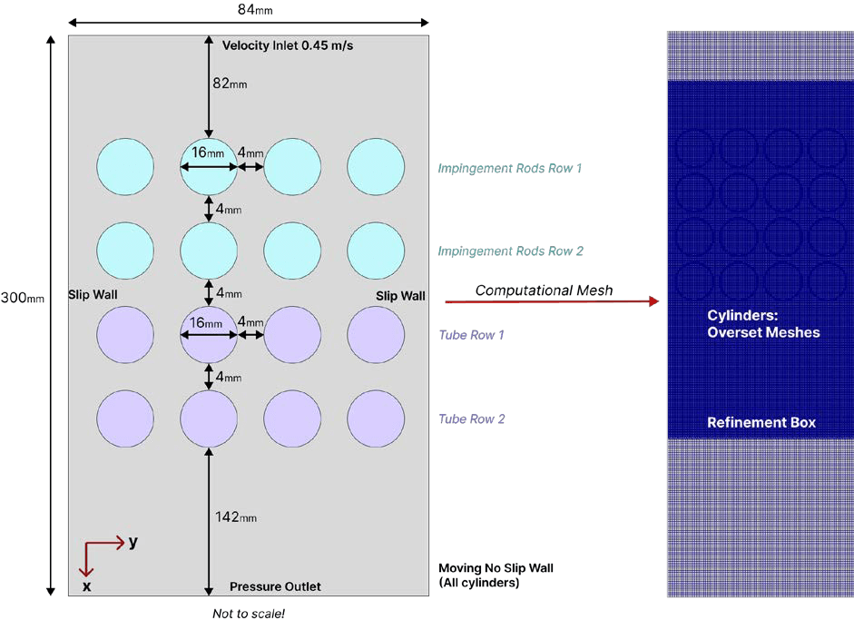
A two-dimensional CFD model was developed using OpenFOAM to simulate turbulent molten salt flow around a representative cluster of tubes. The model geometry accurately reflected the actual heat exchanger configuration, including tube spacing and support rod placement. Mesh refinement was used in the small inter-tube gaps to resolve turbulent flow structures and pressure fluctuations that drive vibration mechanisms.
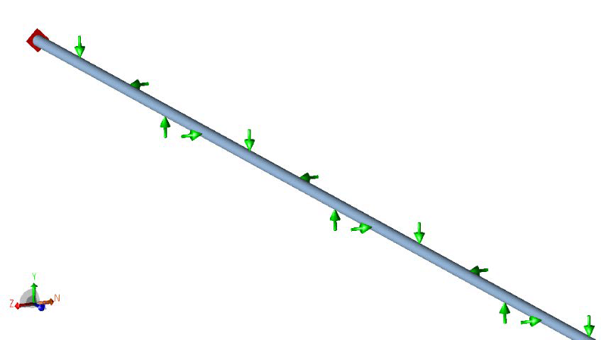
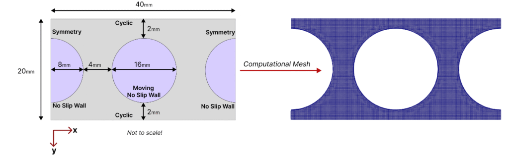
A second simulation was set up using cyclic boundary conditions to study the dynamic coupling of the fluid forces and tube displacement. This used the Caesar II stiffness parameters. The simulation employed a moving mesh technique, which enabled the investigation of feedback mechanisms between flow-induced forces and tube movement.
Simulation Parameters and Load Cases
The shell side inlet velocity was set at 0.45 m/s, perpendicular to the tubes. Five distinct load cases were analyzed, each representing different support rod configurations to evaluate the impact of manufacturing defects on FIV behavior.
Results and Analysis
Vibration Characteristics and Failure Mechanisms
The CFD analysis revealed that the most severe tube vibrations occurred at the free ends of impingement rods, where inadequate structural restraint permitted excessive displacement. Vibration amplitude decreased progressively along successive tube rows, correlating with the decrease in flow velocity.
Quantitative results demonstrated that both impact damage and fretting wear could cause damage to the tubes due to lateral tube displacements under operational flow conditions.

Right diagram: pressure contour

Right diagram: Pressure contour obtained after 100,000 steady-state simulation time steps for Simplified Case 2
Impact of Manufacturing Defects
The analysis identified multiple manufacturing defects that amplified FIV effects. The support rods were fabricated with reduced thickness, weakening their ability to restrain tube movement. In addition, incorrect rod placement resulted in excessive tube flexibility. The impingement rods lacked proper support, allowing their free ends to move. Consequently, these rods experienced more intense vibrations. This in turn can also cause more tube damage due to (1) support rods breaking and the tubes moving more freely and violently due to this; (2) the impingement rods moving violently causes more vorticity in the flow, increasing the vibrations of the tubes.
Conclusions
The analysis demonstrated that flow-induced vibrations, exacerbated by manufacturing defects in support rod systems, were likely the primary cause of tube failures in the heat exchanger.
Engineering Recommendations
Based on the findings, several engineering recommendations were developed to mitigate FIV risks and prevent recurrence of heat exchanger failures. The primary recommendation is to secure all impingement rods through proper welding to tube sheets. Structural reinforcement of the most vulnerable tube rows (near the shell side inlet/outlet) is also critical. Using the first two tube rows as additional impingement elements provides enhanced restraint for the tube bundle while maintaining heat transfer performance.